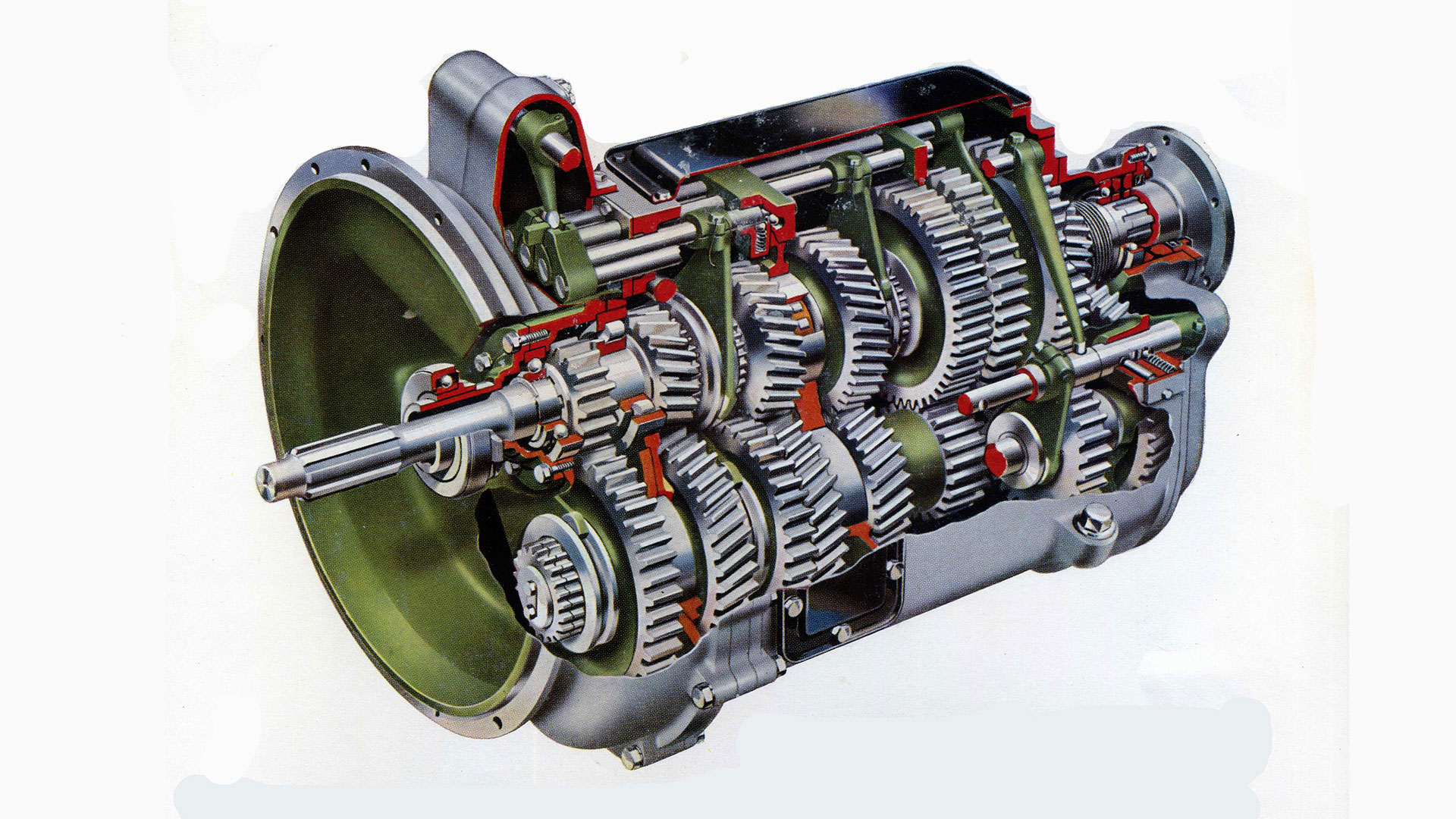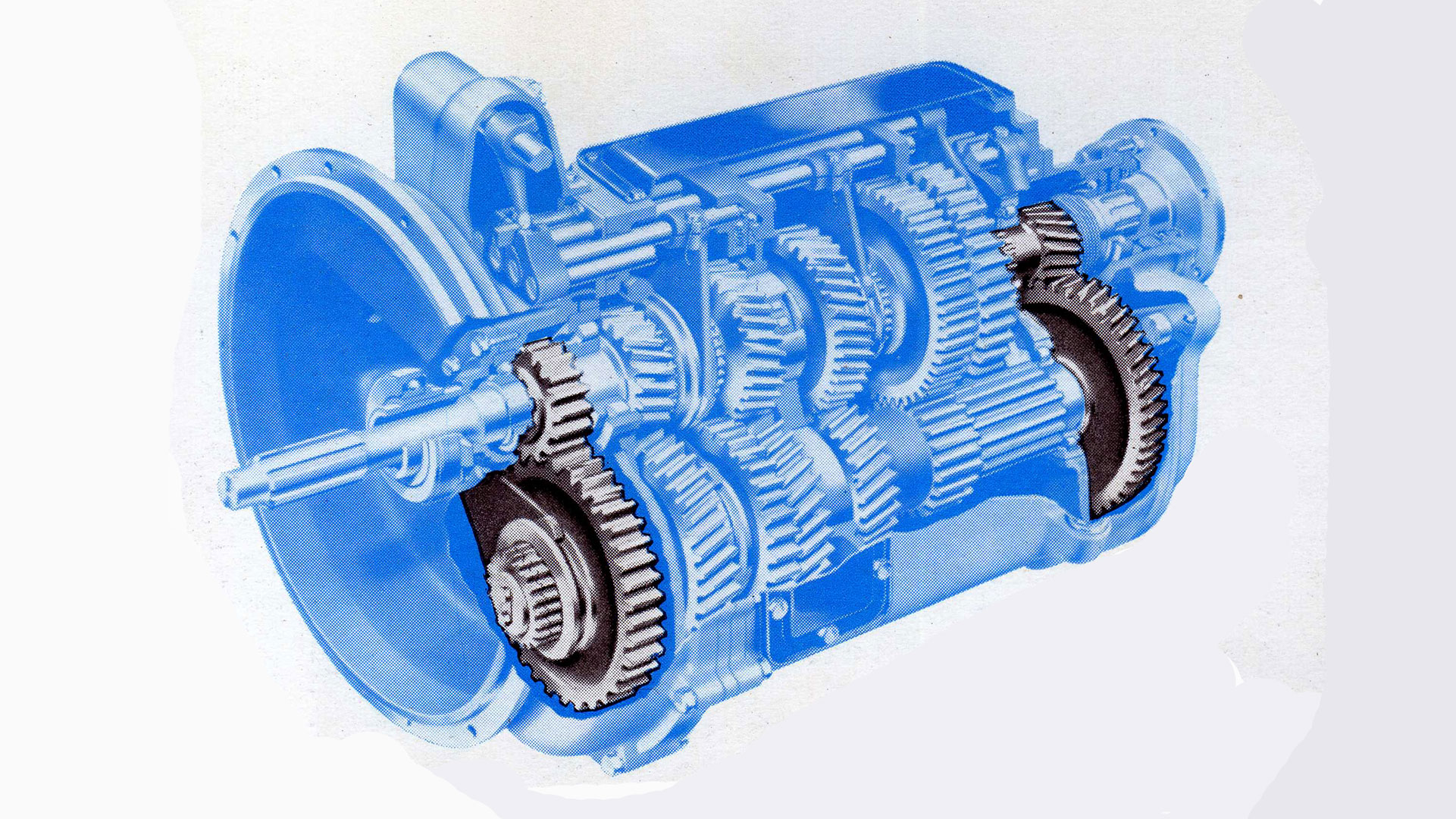


From September 1956 to April 1998Still writing this page, a lot more to come I started in full time employment on 3rd September 1956 as a Student Apprentice at Leyland Motors Limited in Leyland, Lancashire. I was eighteen and 'wet behind the ears'. By lunchtime on the first day I thought 'What have I done?' It was such a come down. For weeks I had been vacillating between choosing to become a Teacher or an Engineer. Writing in 1999 I think, only think, I made the right decision. My 'education' at the 'University of Life' had begun. In 1958 Leyland took over AEC but the companies' design departments remained separate. At the end of my apprenticeship, September 1959, I wanted to work in the Research Department however the Chief Engineer, John McHugh, asked me to work in the Drawing Office and if I wasn't happy after a year I could move into the Research Department then, so I began life in the Drawing Office as a draughtsman. I was given the grand sounding title of Project Engineer. My Section Leader was Jim Milloy, a man I grew to respect in my earlier years. There were three of us, 'Project Engineers' and we were given the job of detailing a new 5, 6 or 7 Speed Heavy duty Gearbox. The gearbox had been designed by an engineer at Albion Motors in Glasgow, part of the Leyland Motors Group, but for some reason it had been passed to the Leyland Design Office to be engineered. It was similar to a smaller gearbox manufactured by Albion. Another draughtsman had started to draw the main gearbox casing, again I don't know what happened to him, and Jim gave it to me to finish, not a very satisfying task but someone had to do it - it was a rather daunting introduction for someone who had little engineering drawing experience however I managed it. It was passed to the Pattern Shop and with their help the casting finally emerged. I was to come to develop a great respect and admiration for the pattern makers, their skill, and who were more than helpful to a beginner like me. The casing finished I started to draw the individual gears. The system at Leyland was to work from an existing drawing so one knew what information was required on the drawing. We drew on plastic film which was durable and easily printable. Once the drawing was passed for production it was traced onto waxed linen. Before drawing each gear set we had to work out the number of teeth using a set DP. During this period I learnt all about gear tooth design and the restrictions placed by manufacturing methods. The gearbox was what is described as a constant mesh gearbox, literally all the gear are continually in mesh but if I remember correctly the reverse gear was the exception. I had to learn how to design the selectors, internally geared rings, to work, i.e. how to keep them from slipping out of mesh.
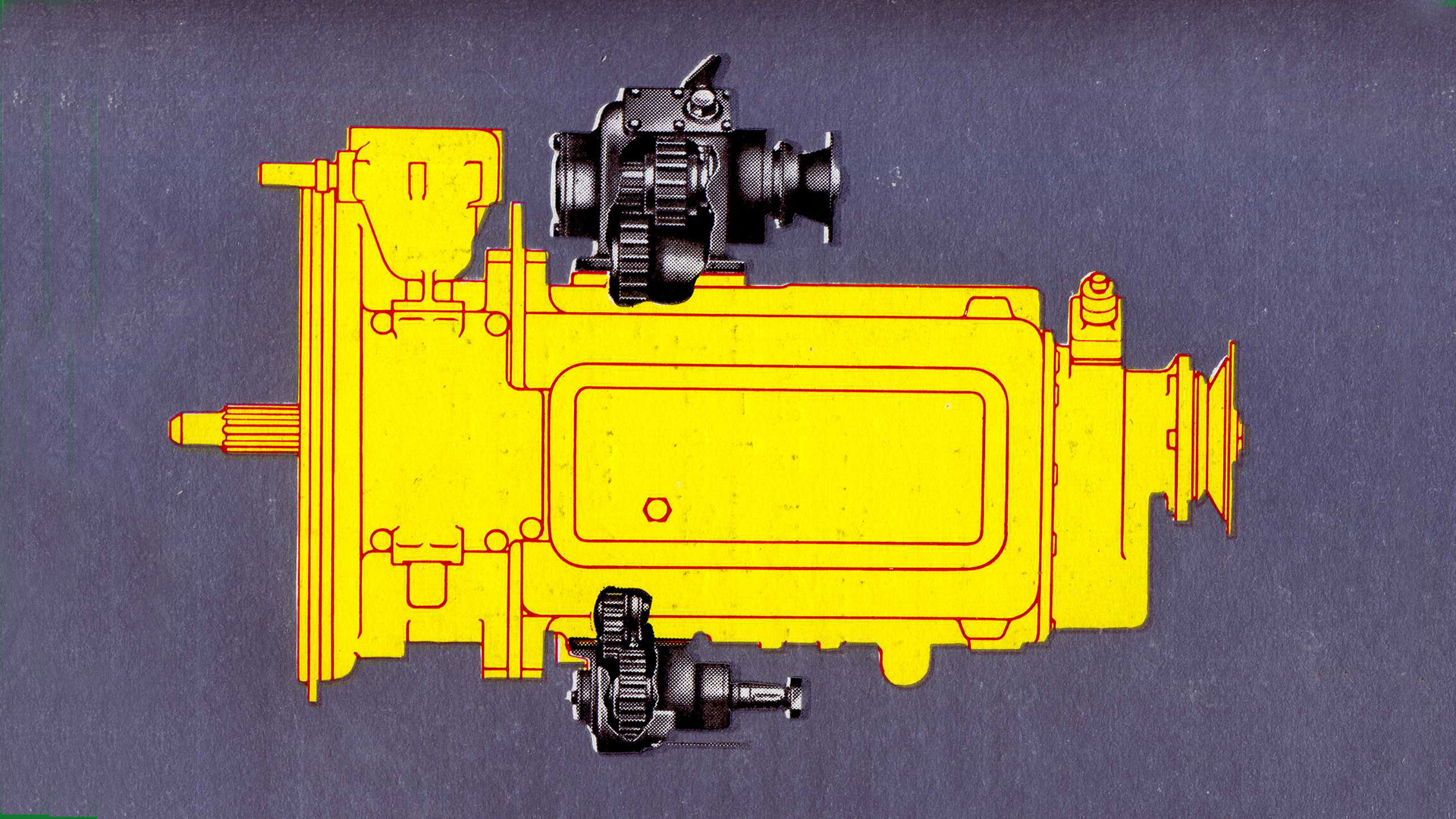
Once all the gears were designed the next job I was given was to design the rear cover incorporation an oil pump from a rear axle. The pump gears and drive from an earlier rear axle gear set were what I had to use and the part of the housing that the gears worked in was copied from the axle. All the time I was learning from previous engineers. The pump was driven from the layshaft as that is always rotating when the engine is running, except of course when you disengage the clutch but then the gearbox is stationary. Next I had to design the power take-offs, two separate drives for auxiliaries on the vehicle driven from the layshaft.
Jim used to say we were 'Space Engineers' not space craft but utilizing the space available in a vehicle envelope. When the gearbox project was completed I was moved on the rear axles
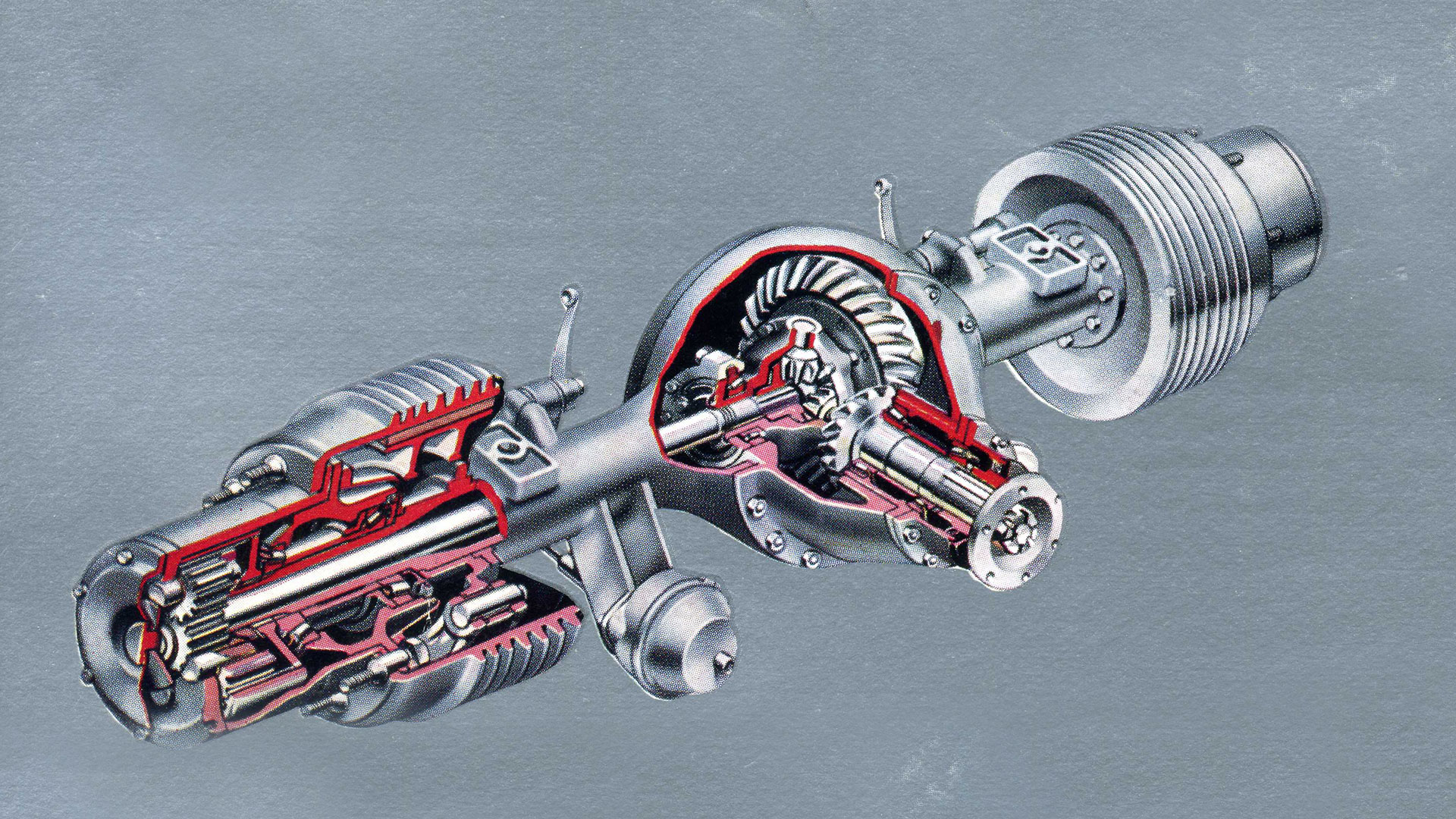
Again it was a new range of axles for trucks (I'd always called them wagons before I worked in the drawing office - my Dad was a Vehicle Maintenance Engineer at Dallas Services which became part of BRS) My memory lets me down here. I vaguely remember detailing all the hub gears and drive gears. The brakes, hubs and differential was a standard Leyland parts used in previous axles and I had to design round them. The hub gears were similar to a lighter Albion axle. I also designed the axle casings. Now over fifty years later I still associate the times I see on our digital clock in the bedroom with back axle specification numbers, 533 in the morning for example.
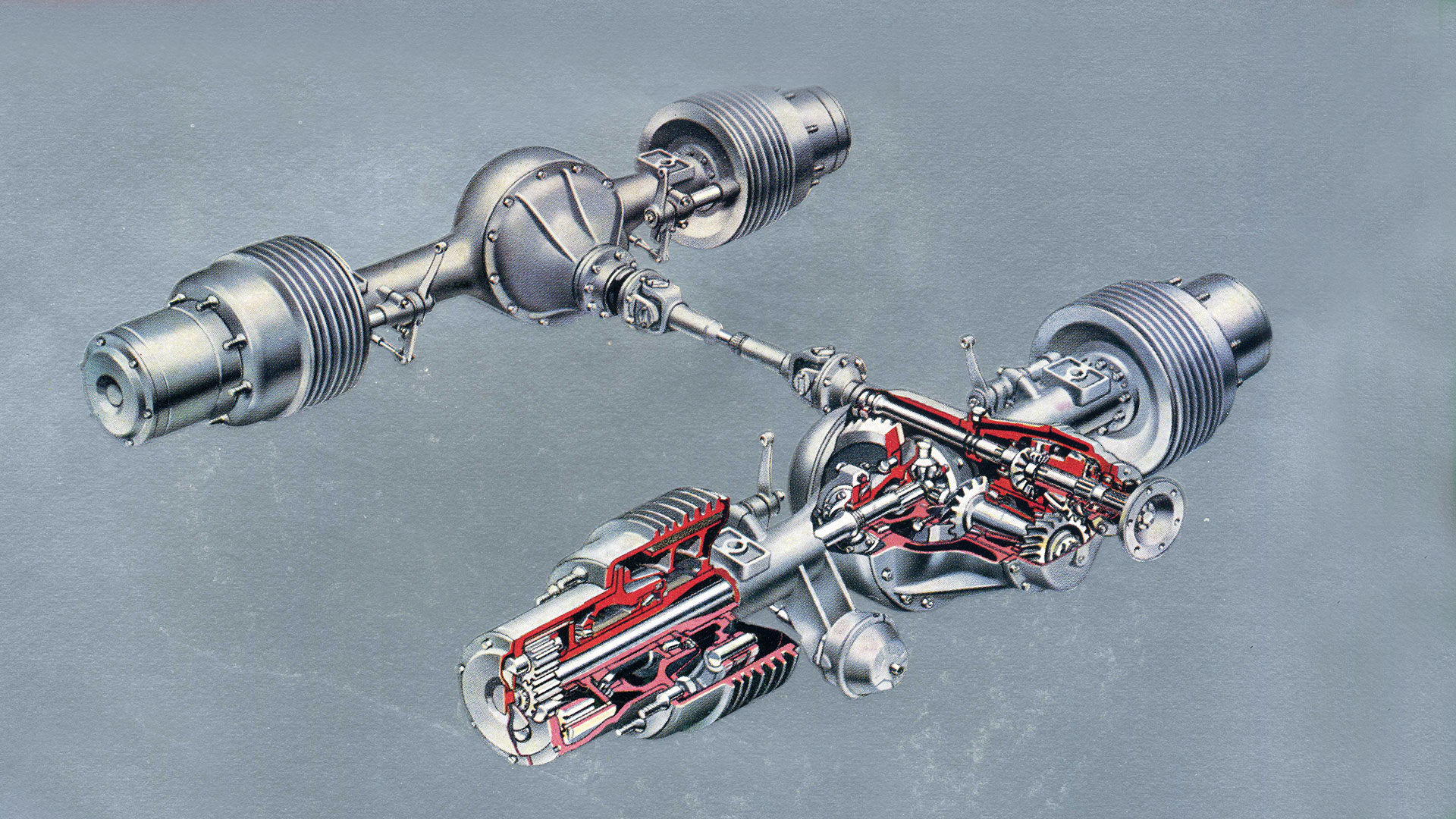
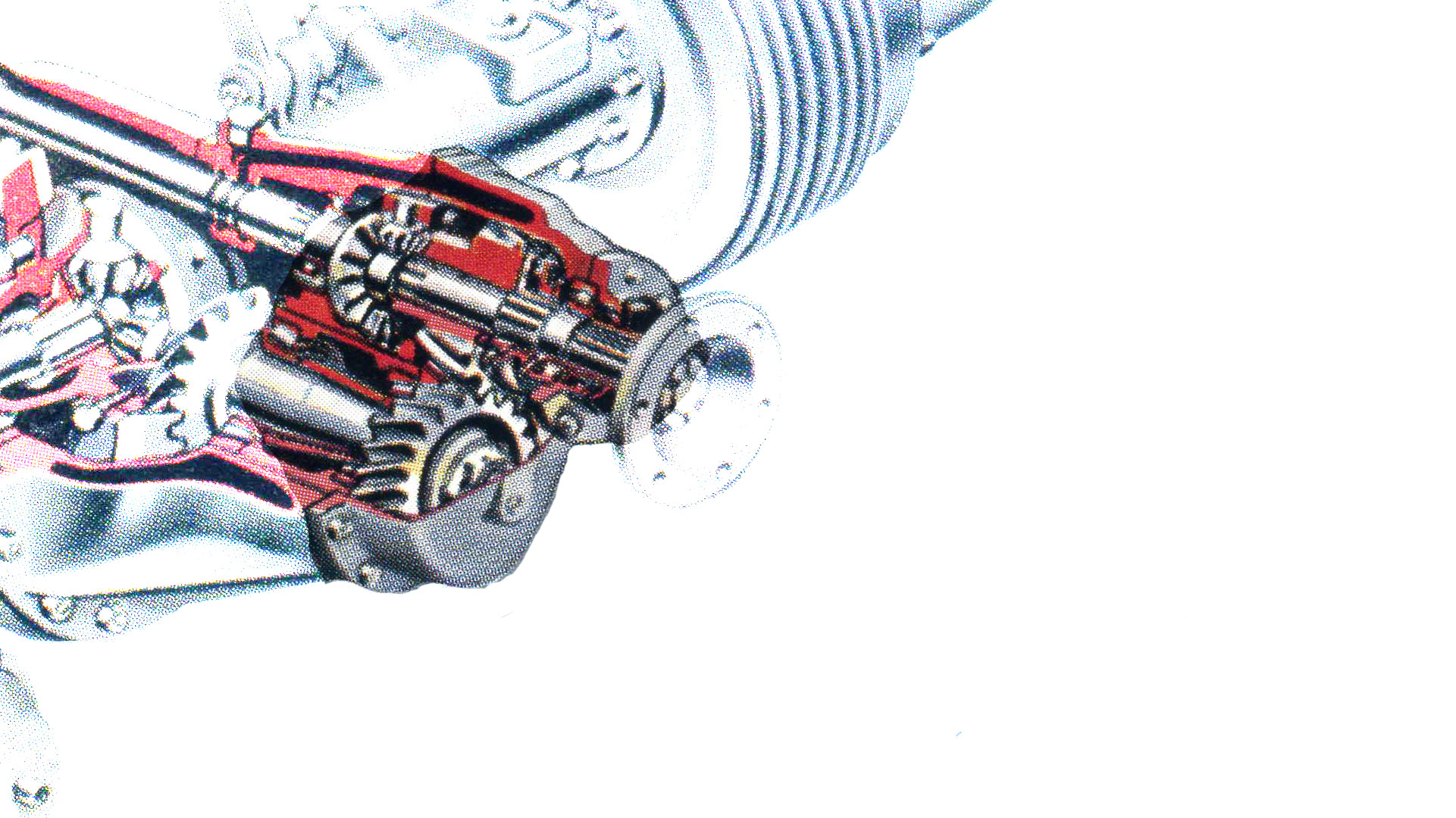
Next we had to design a 'through drive' to make a twin axle drive. Some sort of agreement was reached with Eaton Axles to use their through drive design and we were supplied with all their drawings. We used Eaton two speed axles in all our vehicles. Why we didn't buy the parts I don't know. So a lot more drawing and gear design work. This was where the space engineering came in. I had to fit the new parts into the normal rear axle, the second axle or the one in the image above, adapting the pinon gear to take the new gear train. One of the parts that I'm proud of the the aluminium casing that houses the through drive on the front of the axle.
Early in my first year I was elected a Graduate Member of the Institute of Mechanical Engineers. There was a lot of work designing and drawing out all the variations, even a trailing axle
I hadn't actually done much work on buses. Up to now the design office had been the top floor of the Building in Thurston Road, always referred to as Thurston Road but the design office moved into Three and a half sections of the Spurrier Works H design administration building. Later in the early sixties Leyland took over Standard Triumph to become the Leyland Motor Corporation. For a while it was mostly routine work but I got a job to fit large air brake cylinders on to the twin rear axles on a truck chassis, a task that I eventually proved impossible within the restraints of the specification. Now was a period of routine design work mostly on Wilson gearboxes or as they were designated at Leyland Pneumocyclic Gearboxes. My claim to fame in this period was to design a switch base using a dipper switch for a two speed axle. It made the cover photo of the magazine Engineering Designer, not because of the switch but because of the significance of the two-speed axles. In January 1966 I was promoted to Senior Designer going on to move into the newly formed forward projects department now in the space occupied by the Library in the Spurrier canteen building. The engineers in this department were working on bus code named B7, the future Leyland National. I was given the task of designing the steering box, the box at the bottom of the steering wheel. After completing that there was some doubt about the steering on the axle whether to use a proprietary rack and pinion or design one of our own. Another designer, Keith Blackledge was well on the way with the design so I was given the task of doing the stress calculations in the rack which I achieved and was proud of myself. All hand calculations, computer calculations were unheard of at this time. Actually we were given a calculator a think £300 and it was a huge thing with just the ability to do adding, multiplying and dividing. I was becoming familiar with a wonderful book of formulae by Roark, Roark's Formulas for Stress and Strain, which I used various combinations of the formulae to achieve the result. I wish I could find those calculations, I was really pleased about the way I'd succeeded. In 1968 the Labour Government forced the merger of the Leyland Motor Corporation and British Motor Holdings, to make the last British motor company of any size. That was the beginning of the end.
The design, build and test of B7 was coming to a conclusion so we started work on a new low floor double decker B15. Up to now I hadn't been allowed my position of Leyland's Rear Axle expert but now I was given to job to prepare the concept design of the new dropped centre rear axle. I prepared the original designs for two different new axles doing all the calculations, choosing the gear characteristics after research through papers, books and attending seminars etc.. Bruce Smallbone took over the design of one of the axles and with my guidance he learnt how to design a rear axle.
The canteen was refurbished and became the design headquarters. The final rear axle design was taken over by the designers from Self Changing Gears who had moved up from Coventry.
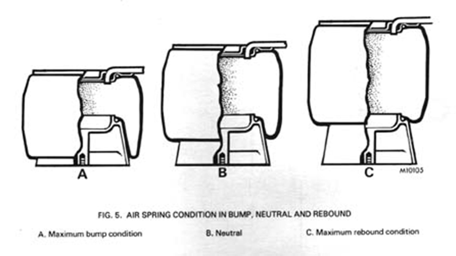
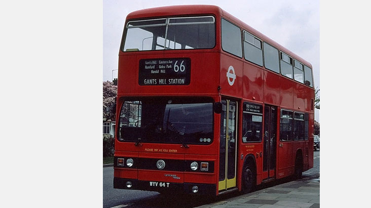
I completed the design and had achieved a suspension which however which way it moved the rear axle always stayed in correct alignment with the vehicle. The Body Division where working hard on an aluminium body for B15 which was being designed to London Transport's specification. The bus was to be built at Park Royal Vehicles in London. We had gone to great lengths to make the achievable floor height over the rear axle eighteen inches but London Transport demanded we make it twenty-four inches! What a waste. After several attempts the Body Engineers could not accommodate the front suspension so I was given the task of designing a structure to integrate the front suspension into body which I did designing a steel fabrication which was to be made at Spurrier Works Fabrication Shop. I was conned a little by our Production Engineering Department who convinced me they could produce a deep pressing to house the air spring. Well several months later we got round their inability to produce the goods. I wasn't particularly pleased with the design but it went into production and as far as I aware it was successful. The B15 is the subject of IMechE paper 1978 Vol 192 No 7
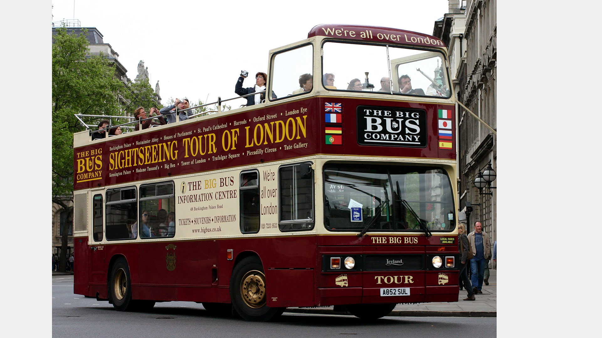
" . . . the Titan really was an impressive piece of design sadly 10 years ahead of its time! . . . " In April 1974 I was promoted to Supervisor, Bus Structures, my first professional appointment, with three designers reporting to me. As a senior designer other designers had been assigned to me but this was the first time that I had had direct responsibility for the management and guidance of technical staff. I was responsible for all bus frames and mounts, including engine mountings and assisted in the introduction of computer and finite element analysis into chassis design.
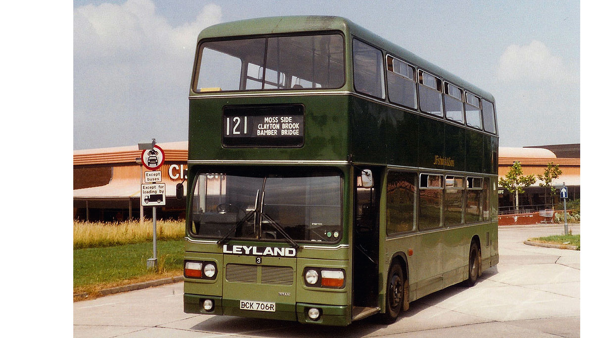
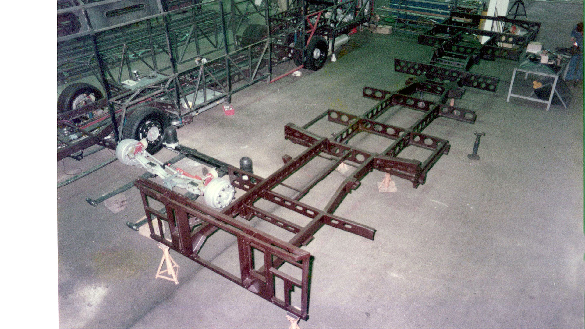
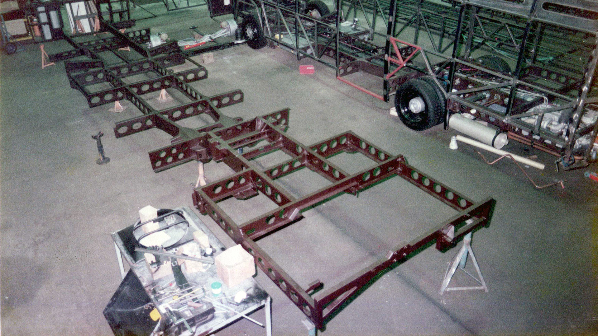
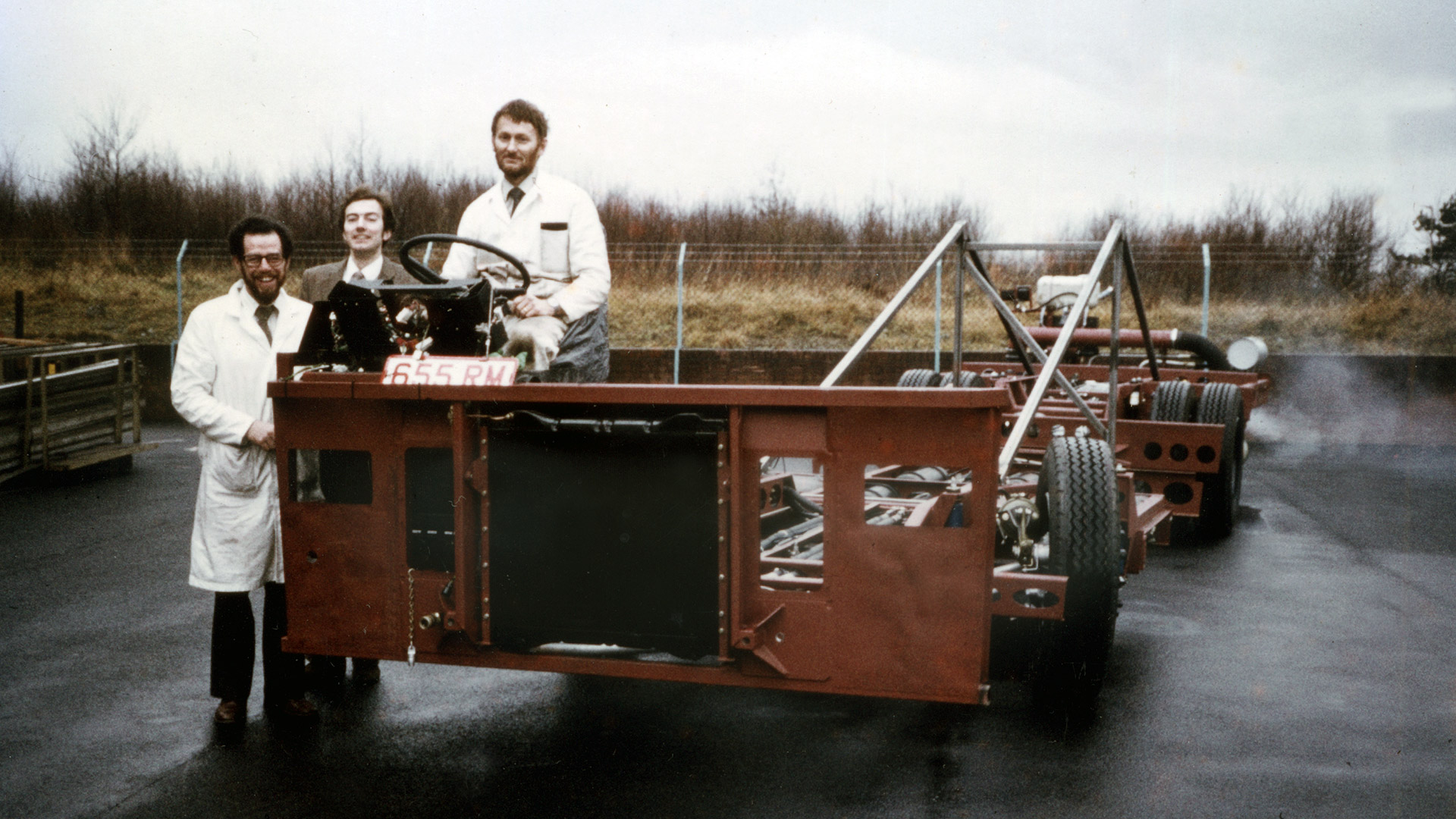
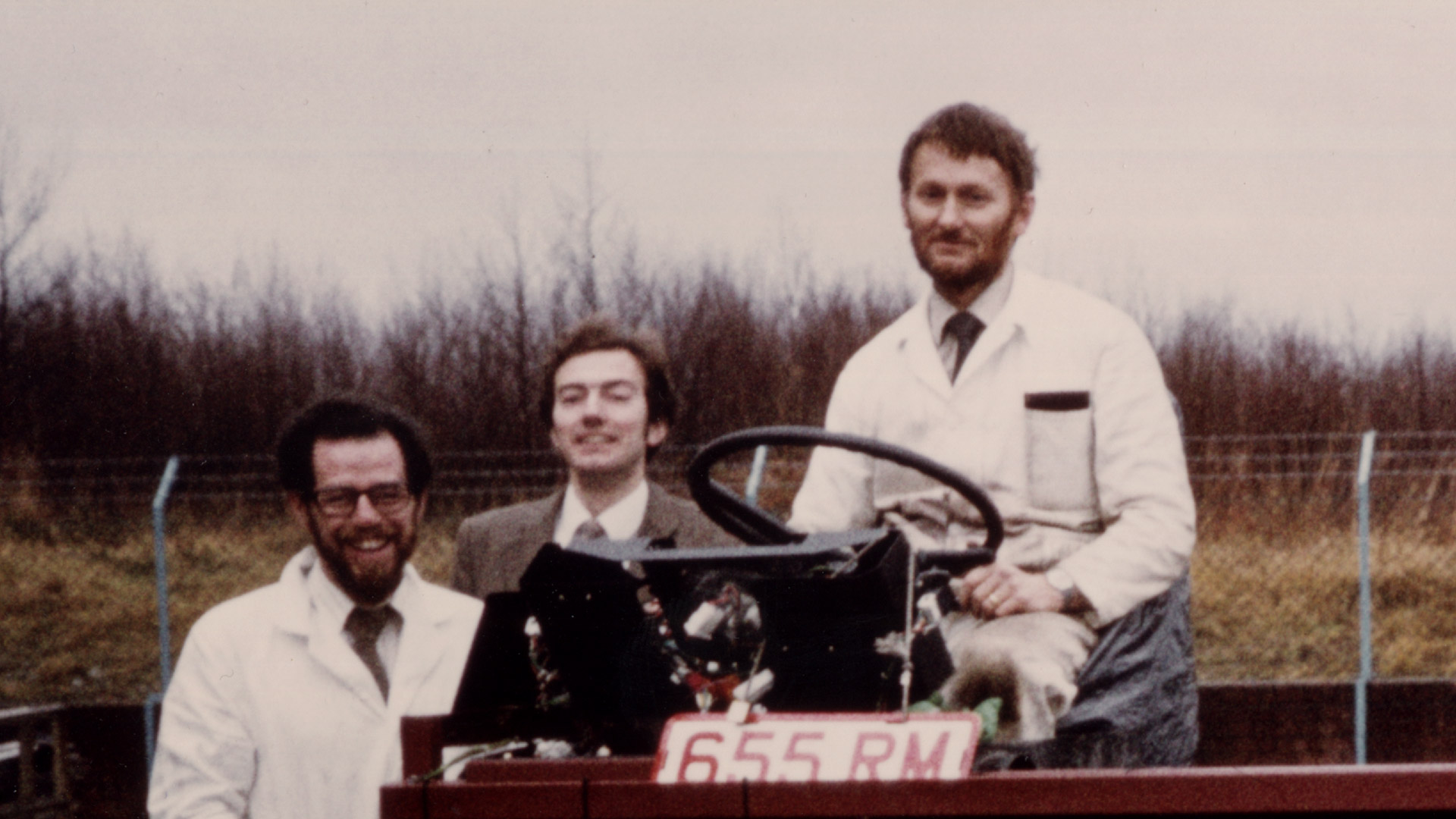
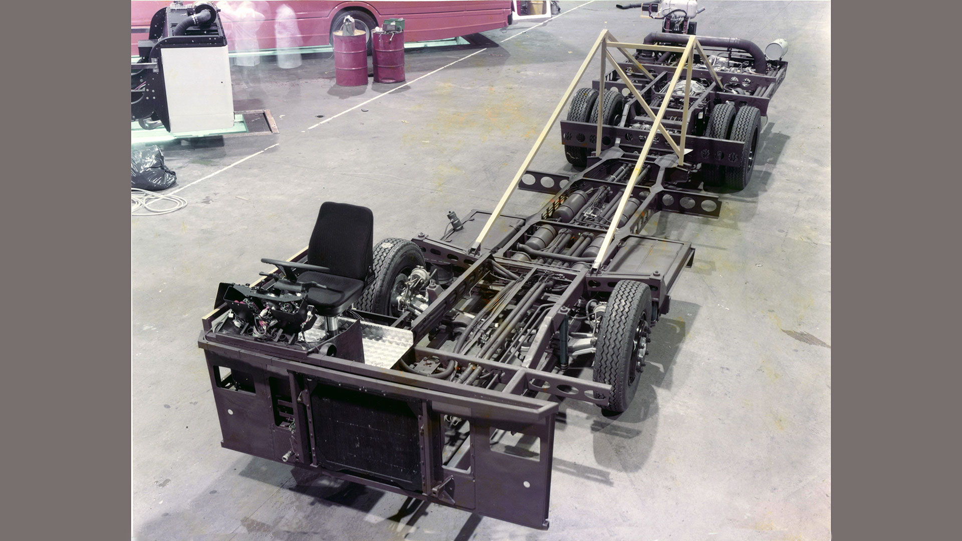
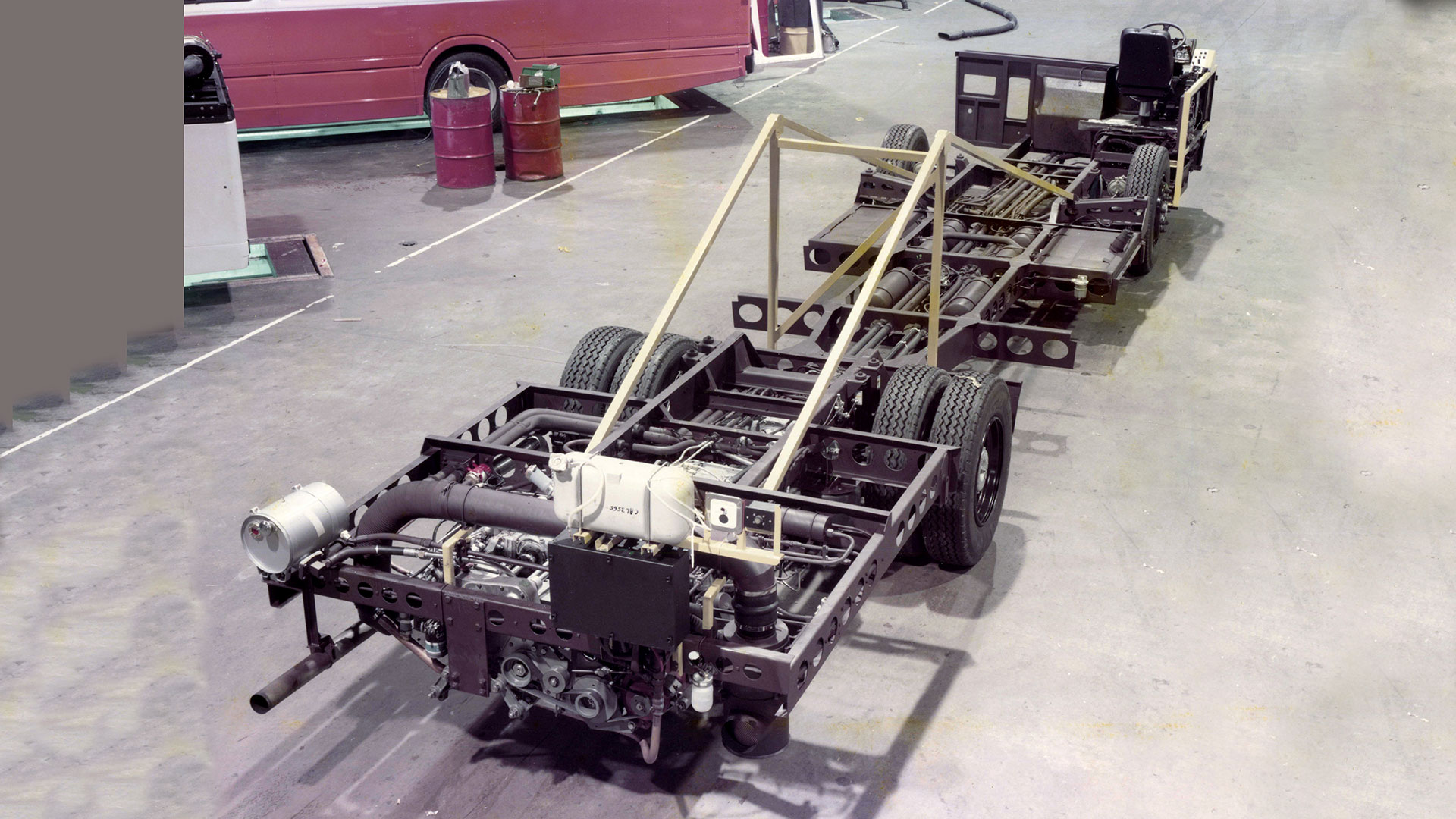
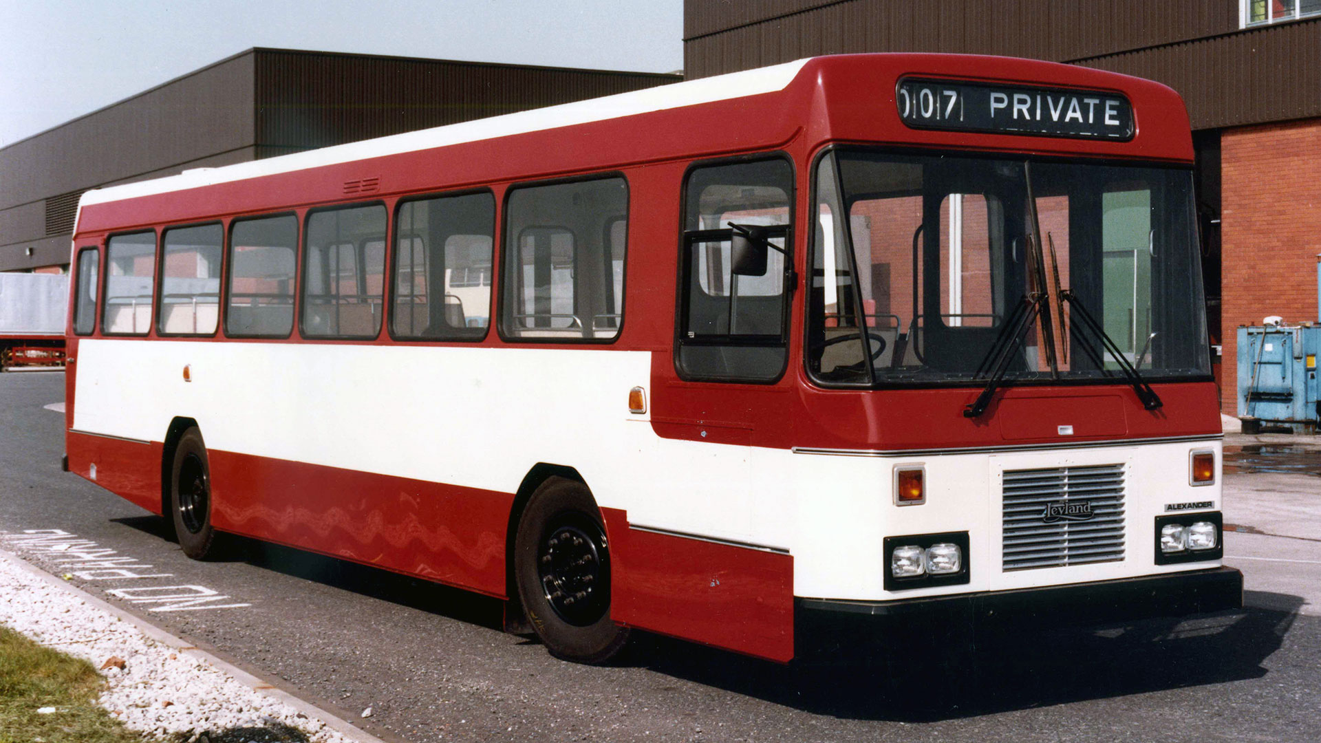
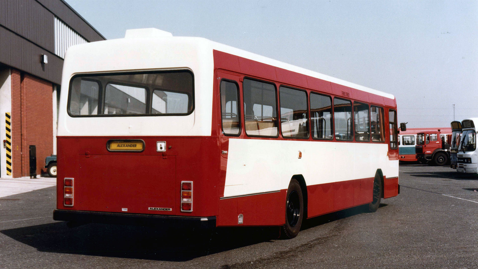
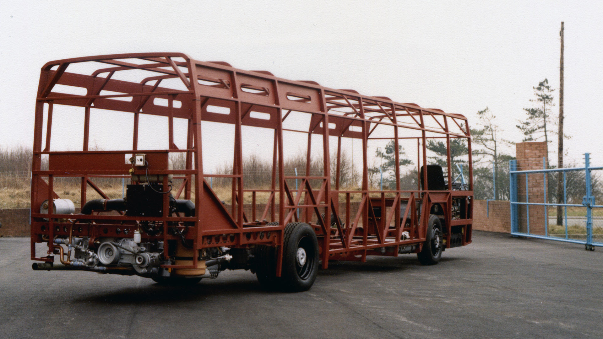
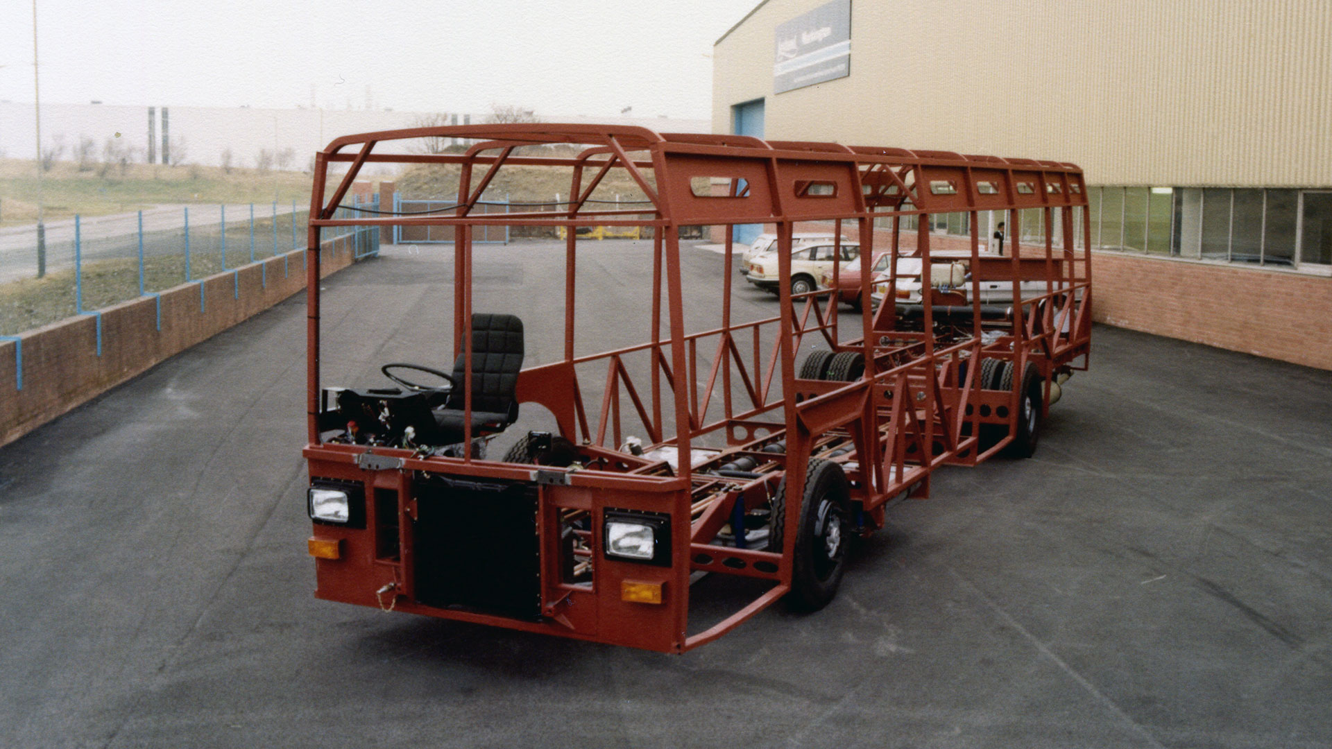
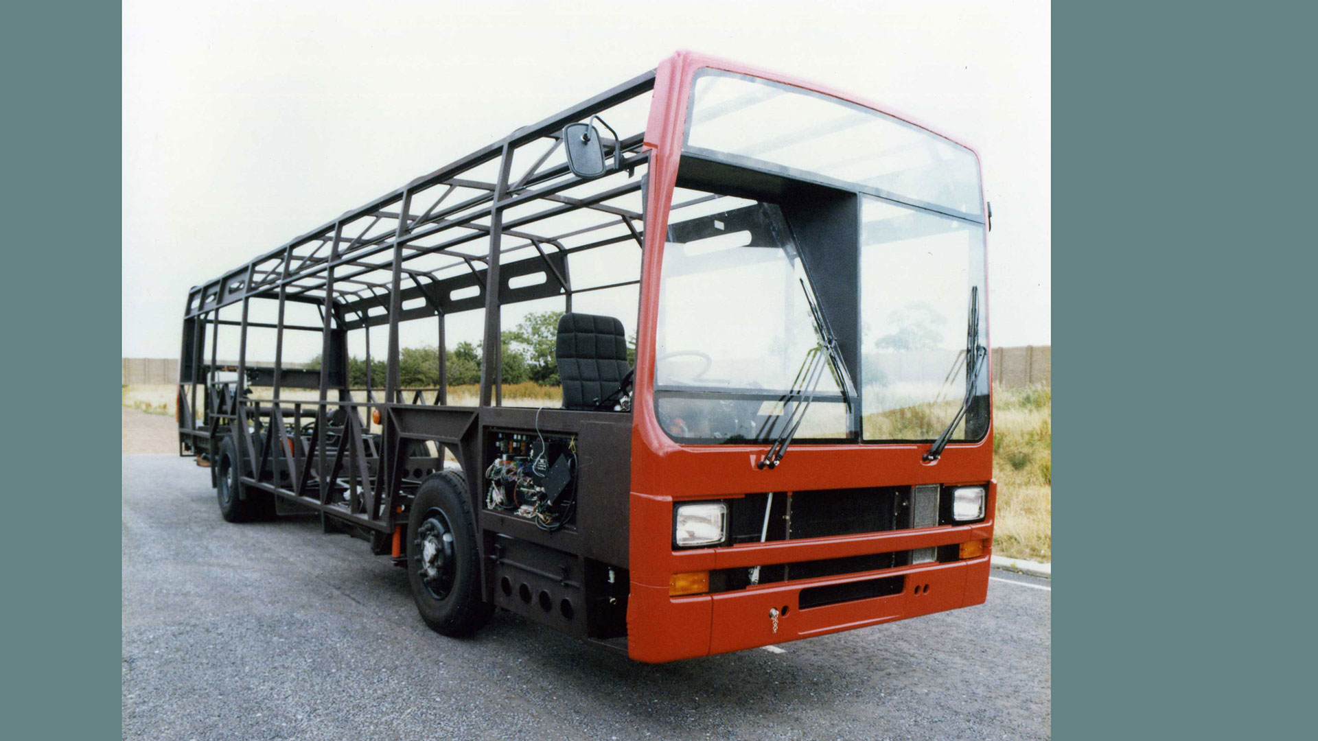
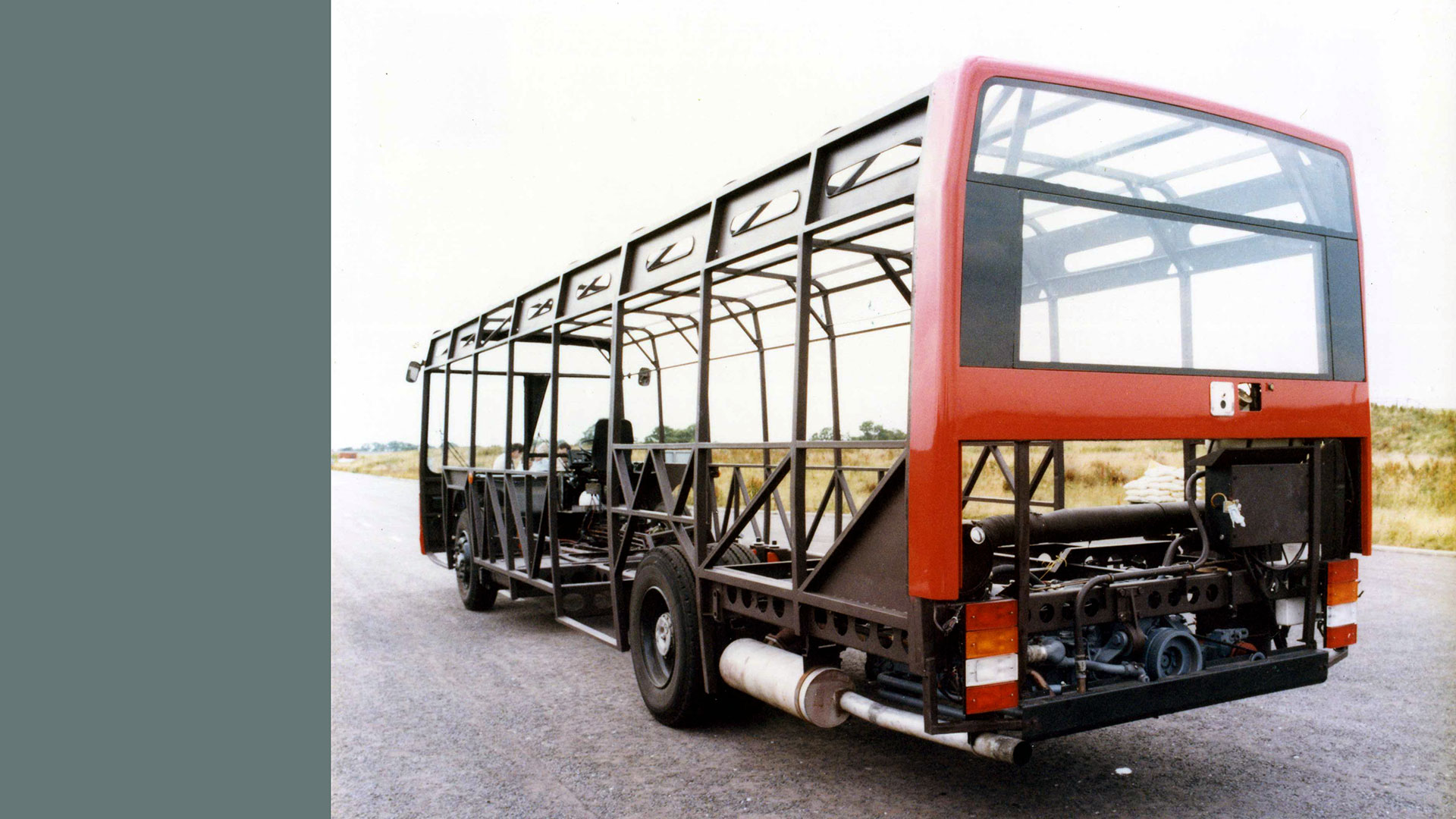
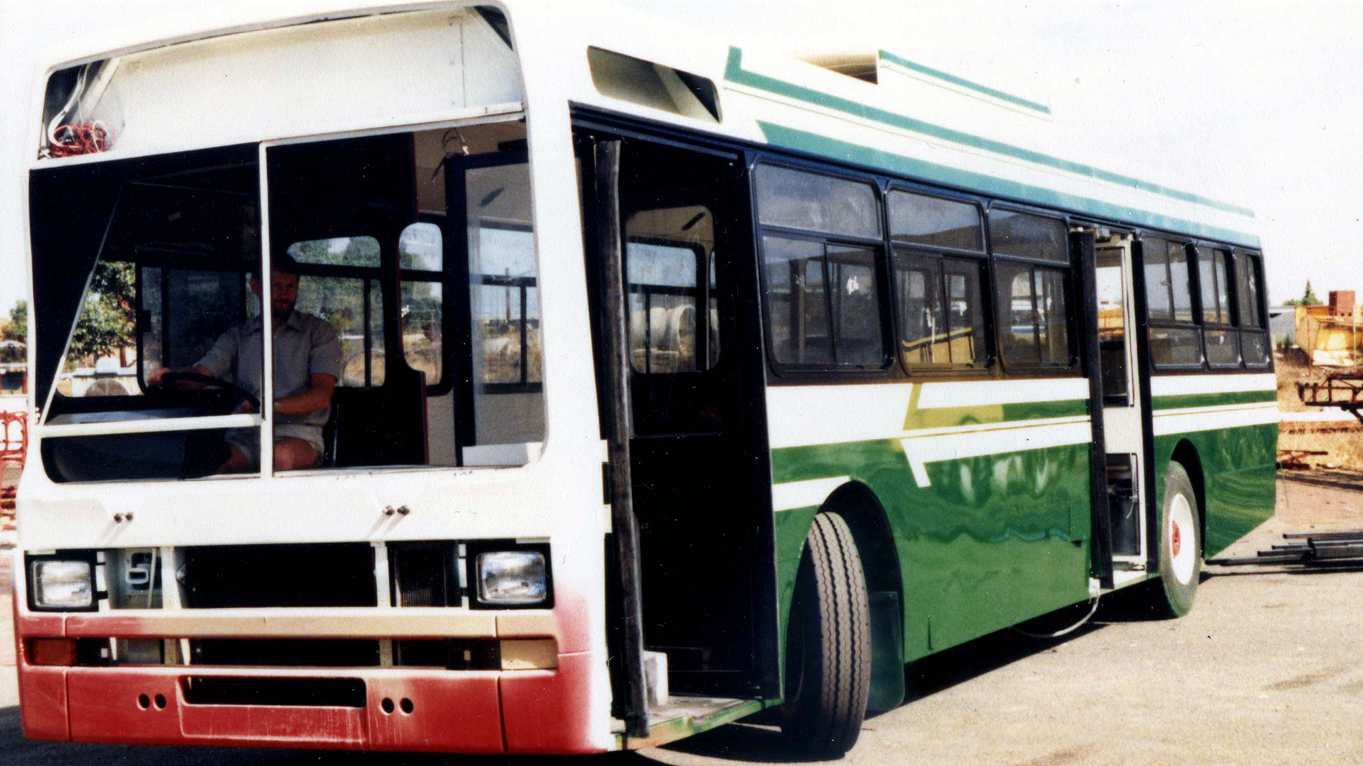
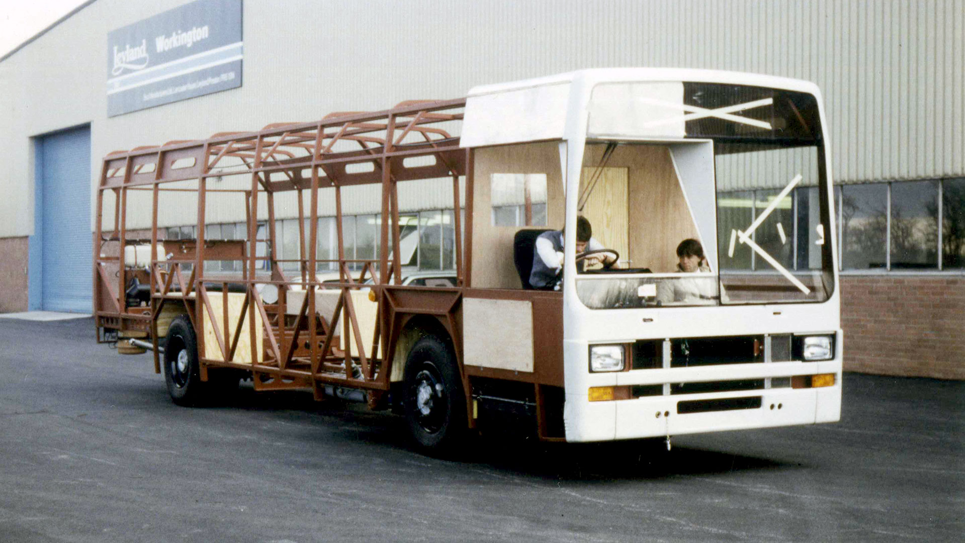
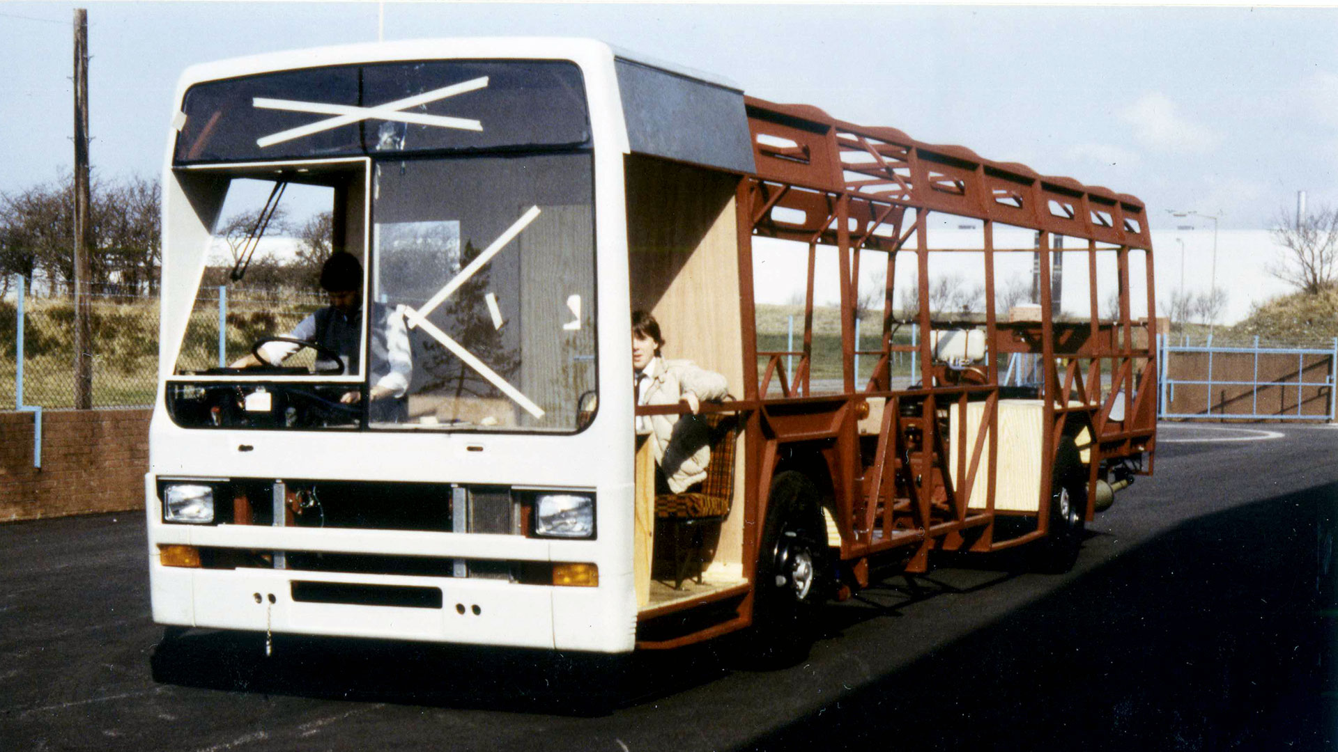
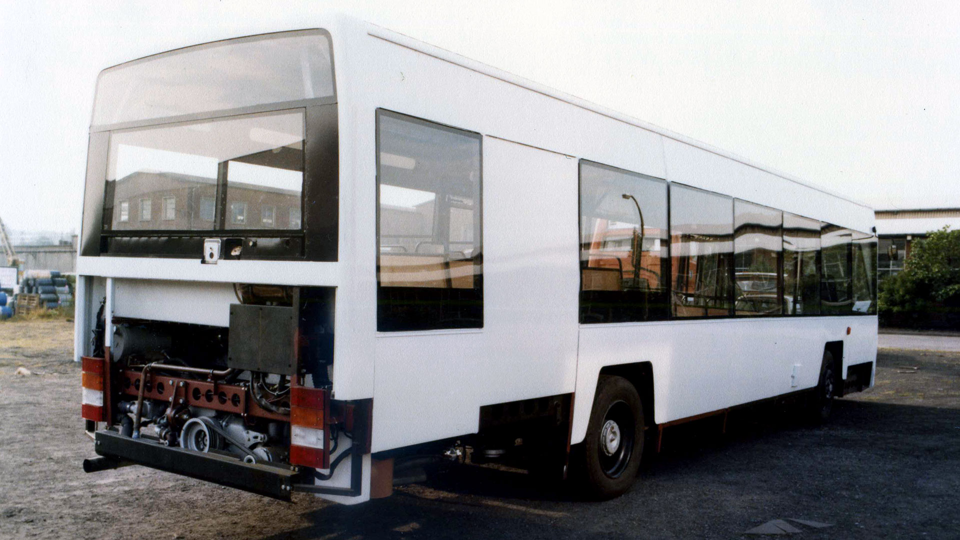
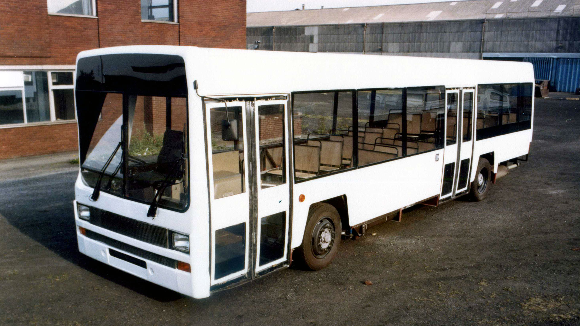
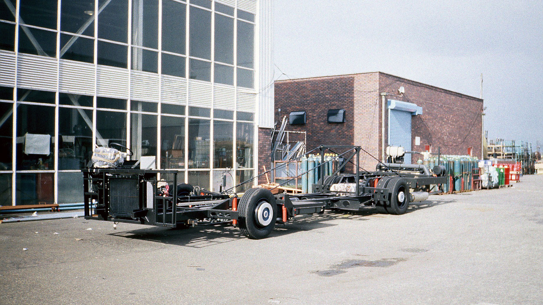
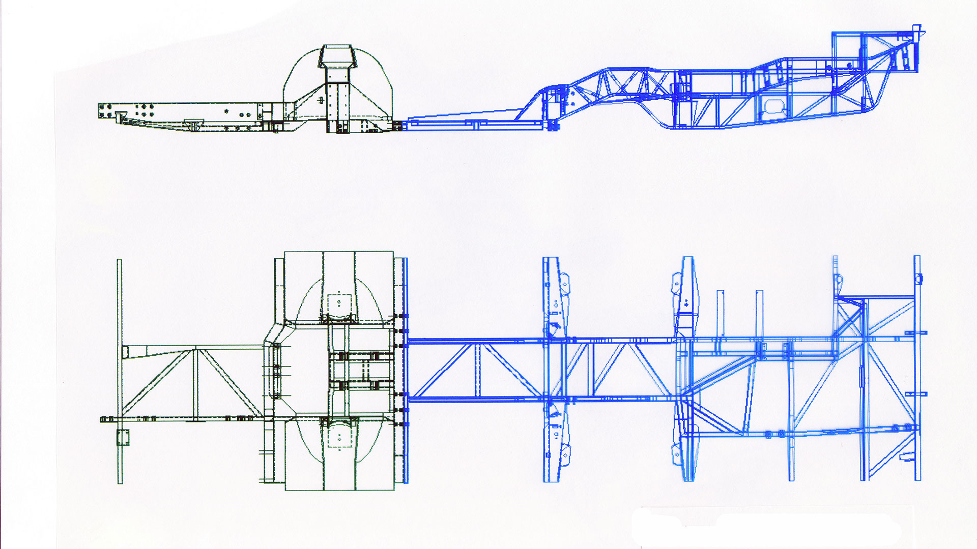
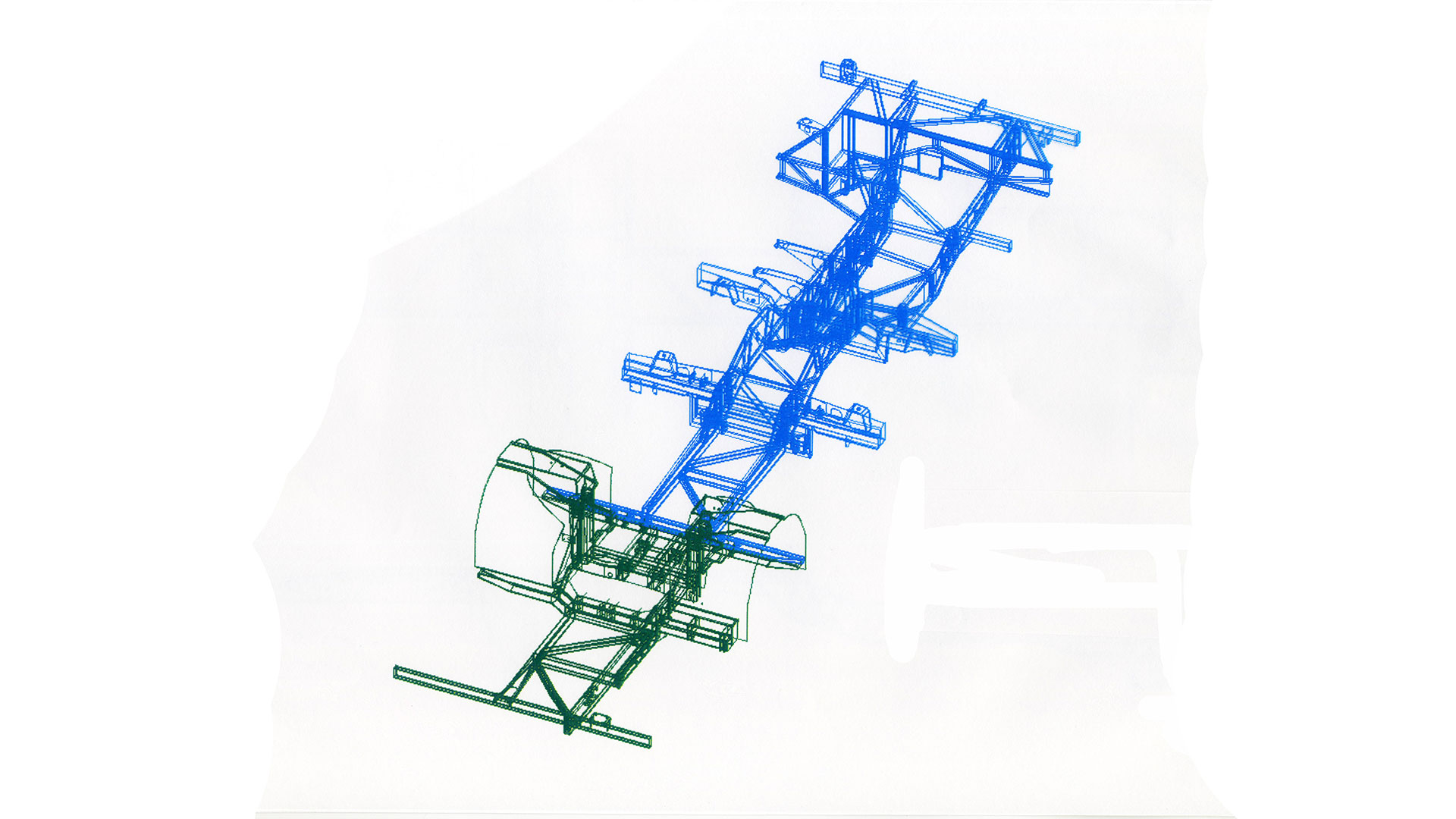
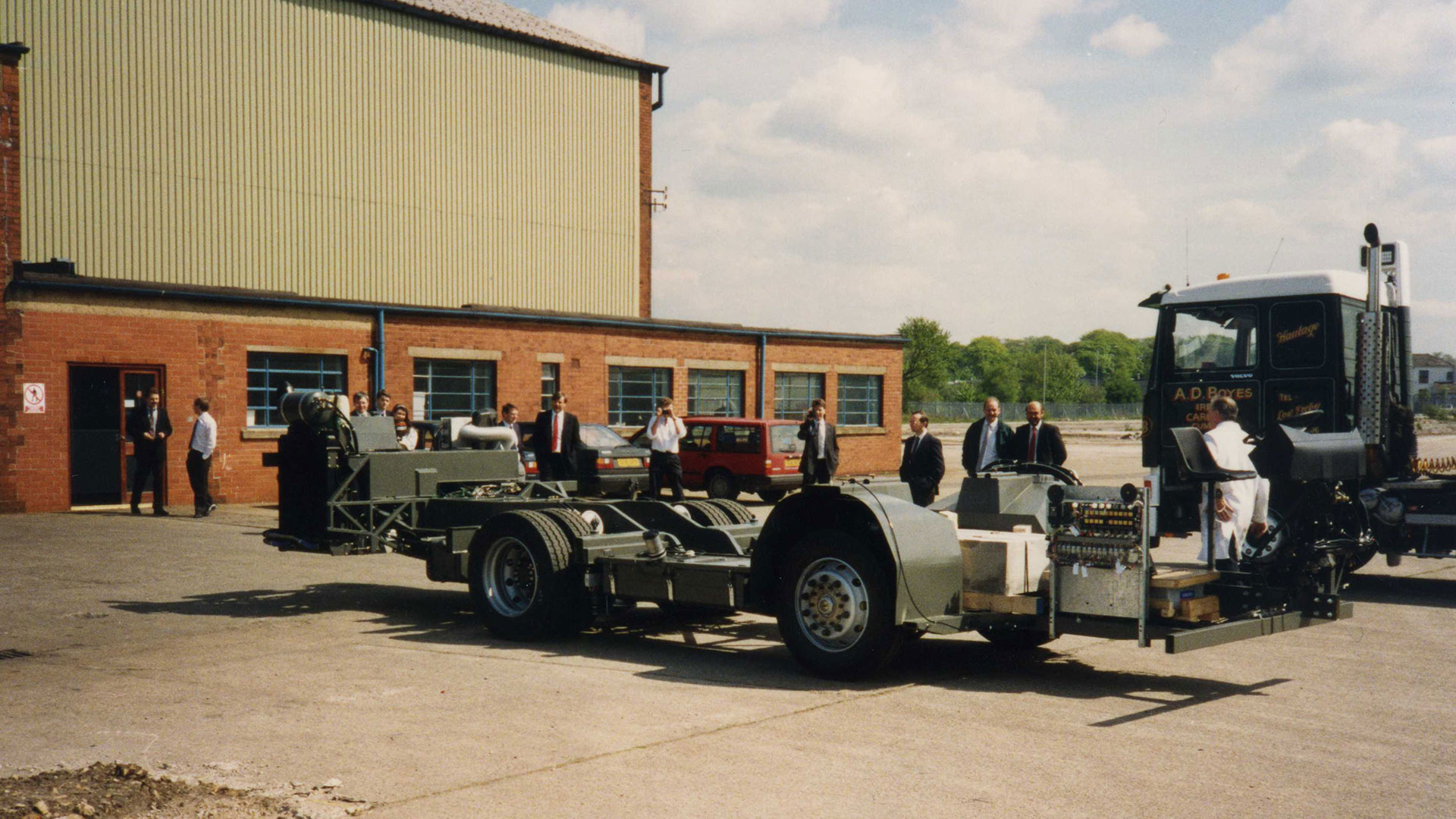
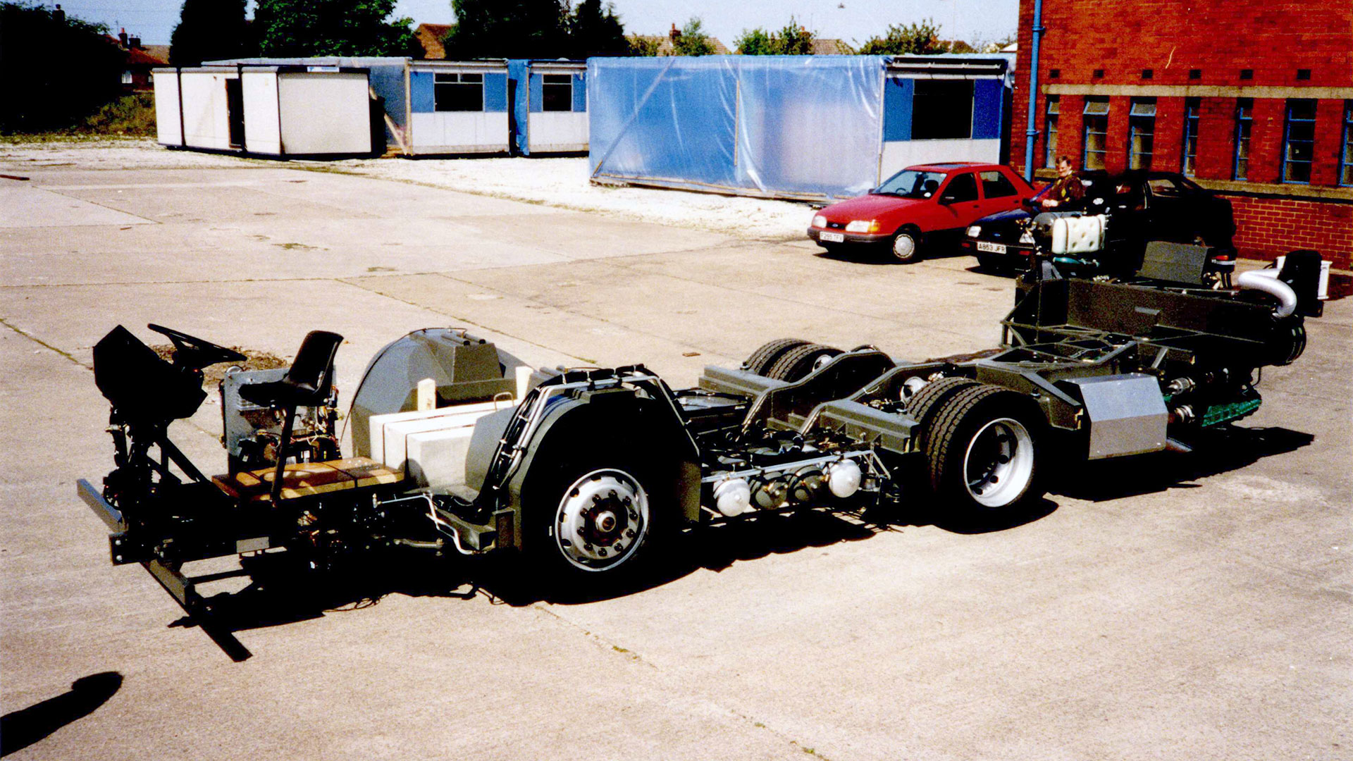
Once the B15, now named Titan was in production, a chassis version was designed. This was done by Bristol Commercial Vehicles, technically I was responsible but the stress ana;analysis was done by one of my engineers, Bill Eccles, did all that. I didn't find it easy to supervise the engineers at BCV so we treated them with respect. I didn't particularly enjoy this position but it came with a salary increase and access to the Management Car Plan. In August 1977 I was promoted to Supervisor, Layouts and Structures, responsible for all bus layouts and structures with three senior engineers and twelve designers reporting to me. At this time I was becoming increasingly involved in human and industrial relations; interviewing, selection, training, development and promotion of staff and on one occasion organised the relocation of the department. Tiger? My memory is a little vague, I'm writing this in 2015, but the Heavy Vehicle Division was broken up into The Truck Division and the Bus Division. As you would expect I was allocated to the Bus Division and we were moved back into the Spurrier H Block. In 1980 I was involved in the selection and purchase of Computervision Designer CAD equipment which we were to begin to exploit in my next position. My next promotion was in December 1982 to Principal Engineer responsible for the design, test, development and introduction into production of our new worldwide city bus, the Lynx, subject of an IMechE paper (C205/86) by my colleague B S Hancock who was responsible for the body. I was responsible for the chassis (illustration 1) having about fifteen engineers / designers reporting to me plus the chassis engineering side of the new prototype department at Workington. We worked together with our teams reporting to our manager who reported to the Engineering Director. The manager took care of the interface between us and Sales and Marketing and customers at executive level, involving us when necessary and helping to present the new technologies we were proposing to the directors and at the same time making sure we kept to the project specification or negotiating any improvements we had designed or changes to targets that we could not realistically achieve. Creating the chassis frame was my major personal design contribution to the project and among my responsibilities in leading the design of the complete chassis were designing the space for all the units, services for the units (piping, wiring etc.), serviceability, accessibility, correct environmental conditions for the units, weight, performance and manufacturability. At the start of the project we discussed with manufacturing the methods of manufacture that were available to us or that would be required. We visited likely suppliers, particularly the company that was to manufacture the frame components. I organised my staff to consult with the experts available to us within the company and outside e.g. legislation, ergonomics etc.. Some of our designers were either young engineers in their first appointment or designers inexperienced in chassis design. I allocated the work to suit their abilities and in such a way as they could develop as engineers and designers, using my knowledge of engineering and engineering principles. I planned the work so that the long lead time items were designed first and arranged for the ordering of all the material for prototype vehicles, spares and for use on the test rigs. Although we had a clean sheet of paper it was my responsibility to see that we made maximum use of existing components and not create any unnecessary new parts.
For the first time I had more practical skills than the actual workforce at Workington. At Leyland the craftsmen were infinitely more skilled than me. I remember welding up the exhaust pipe, gas welding one of my better skills.
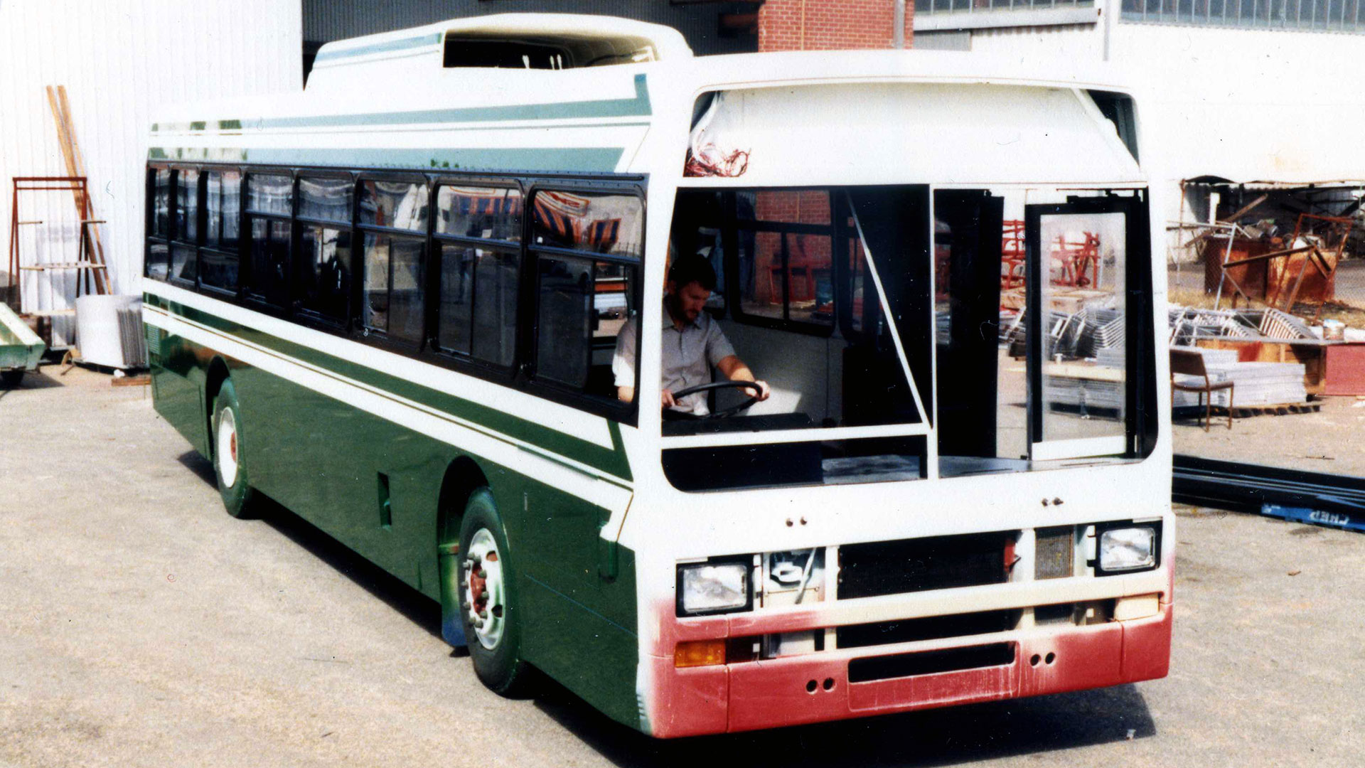
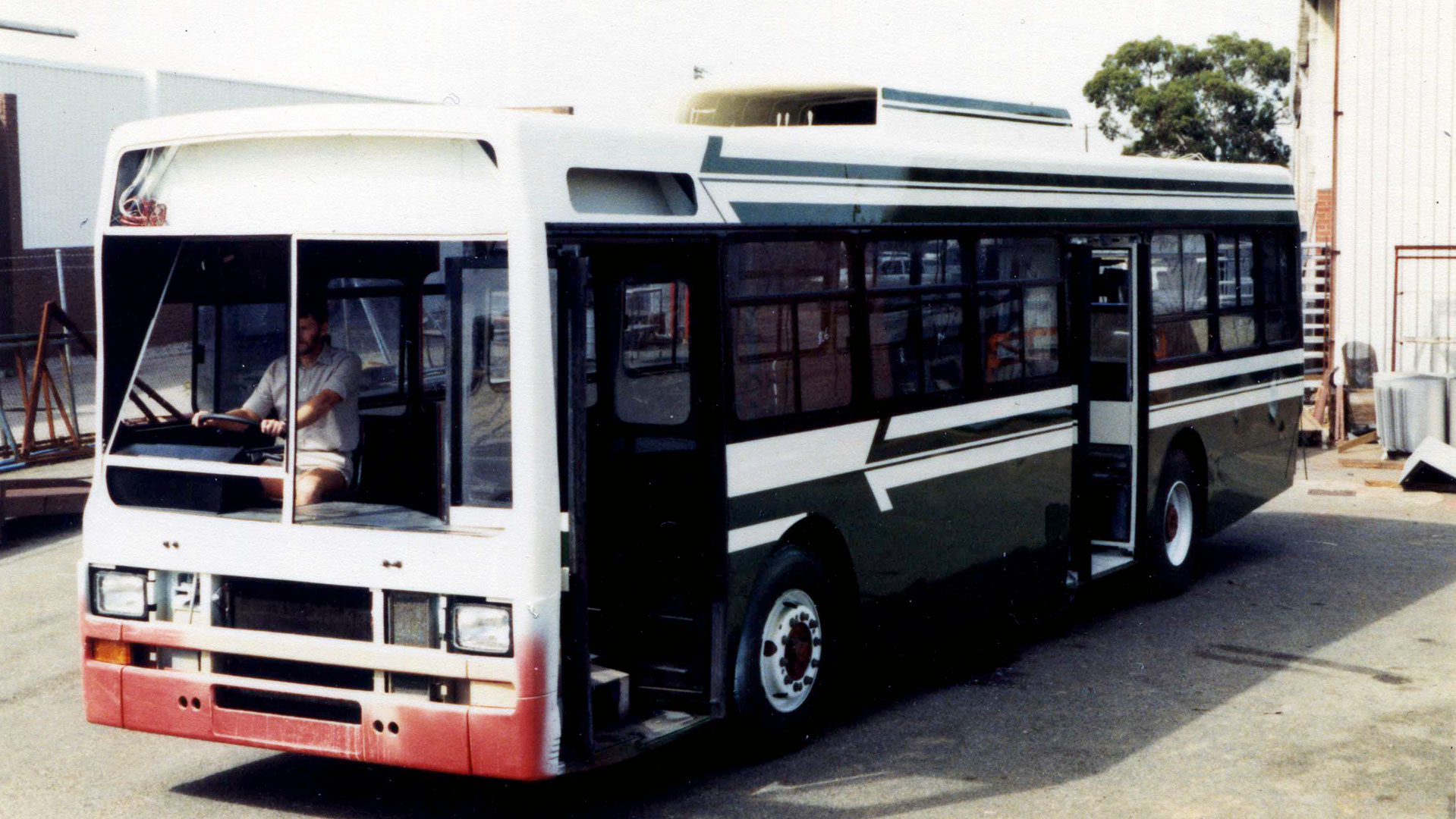
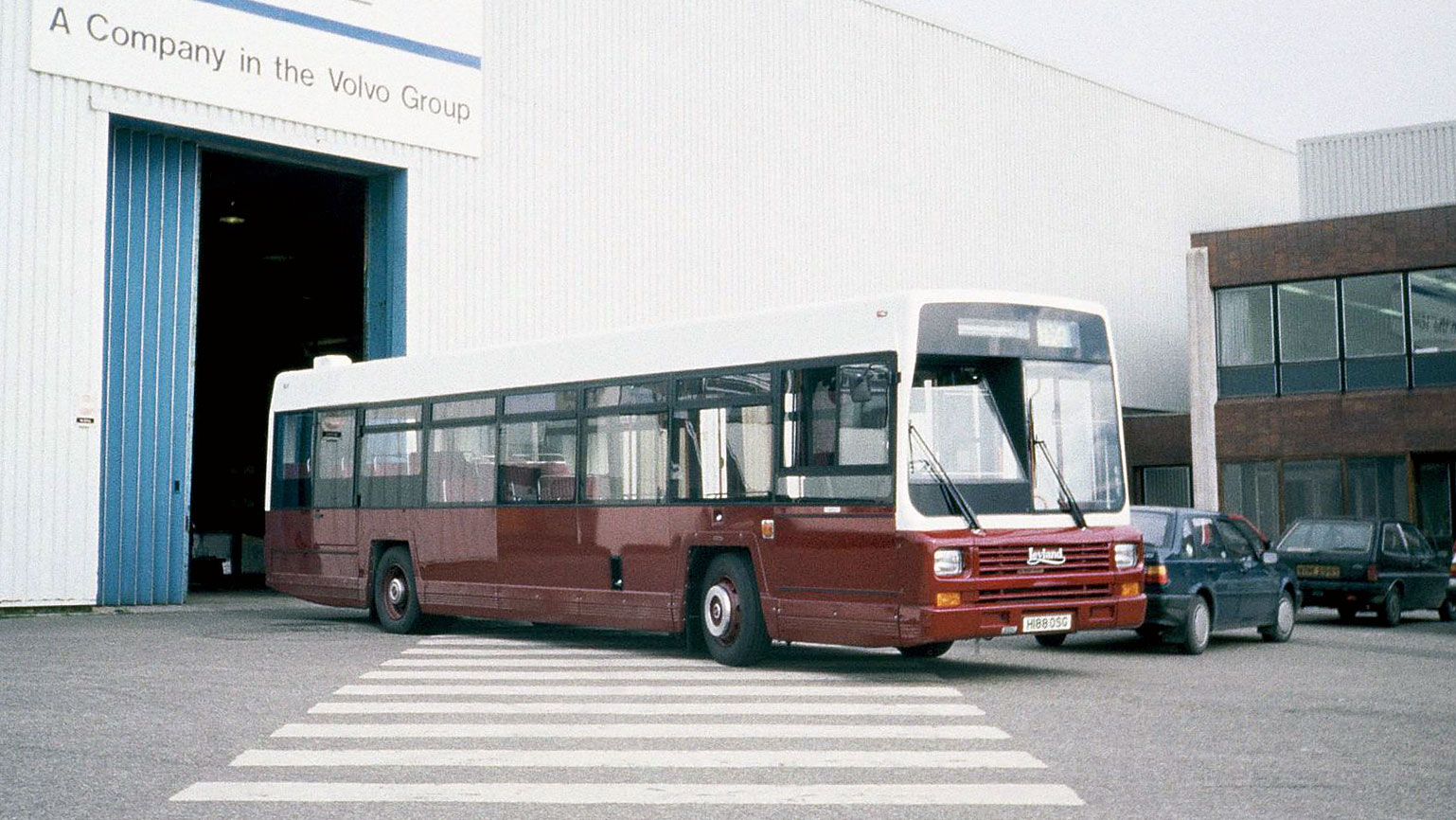
The first prototype arrived in Belfast on time. During this time I was involved with the sales and marketing of the bus and I spent some time with sales personnel, customers and the bodybuilders in Ulster and Perth Australia where the first two prototypes were respectively bodied.
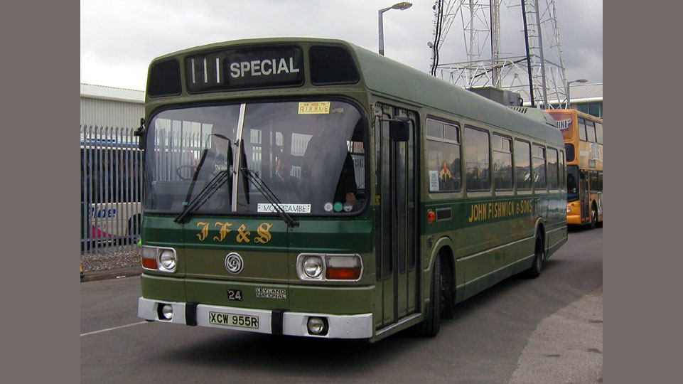
The Lynx now established in the UK and being considered for Europe. The Perth venture was not a success - the Chief Engineer of Perth was anti-Leyland for reasons probably buried in history. We had a demonstrator in Singapore creating interest in the Far East. We have had a few structural problems, sidemember crack and rear engine mounting crossmember failure, operating in Merthyr Tydfil but these have been satisfactorily resolved. John Fishwick & Sons Leyland Lynx 14, J14JFS - A video showing Leyland Lynx J14JFS from the John Fishwick & Sons fleet. At the time the video was filmed this was one of only three Lynxs left in the…
A restored Lynx and another video
British Leyland was privatised. No company was prepared to take on the Bus division so we came to being closed down. There was a management buy-out and Leyland Bus was formed. Now we returned to the Thurston Road Building, the Engineering Department was back on the second floor. We were now governed by ex-Bathgate people, The Bathgate Mafia as we came to know them and we were weakened by some of Ford's cast offs. My first engineering problem in my new role was to fly out to Singapore in 1984 to approve the fitment of a body, designed and manufactured in kit form in Scotland, onto the Olympian double deck chassis. In two weeks with the Singapore Bus Company's Engineers and a body Engineer from the Scottish bodybuilder I had to negotiate, as the Leyland Bus Chassis Engineer, acceptable design compromises and convince the customer that the vehicle was structurally sound. In September 1986 there was a massive reorganization and redundancies. I narrowly escaped because a friend decided to accept the redundancy and I got the job earmarked for him I was appointed to the position of Principal Engineer on Design Analysis, a new department developed out of the structures and materials department to bring together specialist knowledge and design experience to strengthen and broaden these into new fields and at the same time enabling fewer people to be employed in the area.
The inspiration behind my appointment was that I would be able to use my knowledge and ability to filter engineering problems producing solutions relatively quickly and cheaply allowing us to concentrate our time on the difficult problems. I report direct to my chief engineer, who allocates my work and to whom I report work progress and completion, as one of the three principal engineers making up the department. There are about fifty engineers / designers who rely upon us for leadership and guidance on engineering problems, analysis, materials and in my case design. Our computer programs are supported by Istel and our own engineering services otherwise we are completely self reliant. My responsibilities include the leadership of the design of chassis frames and frame structures including in depth structural analysis, using the latest finite element techniques, and complete vehicle structural analysis. I apply scientific methods and outlook to the analysis and solution of engineering problems including original design and major service problems. I have to develop a thorough understanding of vehicle structures with special consideration to their influence on vehicle design. I am responsible for keeping abreast of new manufacturing methods and materials and to improve design and analysis methods through the creative use of new technology. My next engineering problem was to analyse the design of a new heavy duty front axle beam. We have load conditions which have evolved over the years as have our methods of analysis and for a long time "belt and braces" designs have been created, but today we need to design to greater efficiency. I did my first serious structural analysis in the seventies on a rack and pinion steering gear using hand calculations. All my gear calculation previous to that time, although done by hand and involved, were following established procedures and the actual calculations did not require much intellectual effort. Since then from time to time I have been responsible for structural analysis but this was performed by the engineers and designers reporting to me. To bridge the gap I attended Nastran and Caeds courses at Istel so that I could combine my experience with the latest new technology and have continued to do so. The computer aided FE methods allow greater depth of investigation but they are not absolute. I took the existing beam and prepared a complex model (illustration 3). I used the knowledge of the use of the CV CAD design facility to prepare the geometry base of the model using the same data base that the designer had prepared transferring the model to the Istel Meteor system where we use Caeds and Nastran to do the analysis. This was another first for our company. Today my colleague has carried this further and we now prepare the finite element model on the CV system and write the Nastran file direct. I subjected it to all the known loads that are experienced in service. These loads are obtained by fitting transducers to existing vehicles. There was not time to do this so I had to research reports of previous tests. We had not the facilities to even subject the existing beam to simple deflection tests at the time so to proceed I had to make engineering judgements. Particular attention was paid to areas where the existing beam had failed. I prepared the new model (illustration 4) did the analysis comparing the results and proposed engineering changes or confirmed the design where it was acceptable to allow development of the design. We had to be right because we had to commit to production tooling to produce the prototype beams. I have colleagues to whom I can approach for information and discuss ideas with but at the end of the day it is my responsibility to provide design information. The axle, although not in series production yet, is successfully proceeding through the test programme. In the spring of 1987 I was given my next engineering problem which was to design a chassis frame for a new concept of a minibus from a written specification and a thumbnail sketch. I produced a chassis frame design starting the iterative process of design - analysis - design etc., (illustration 5). The project was given to my Chief Engineer and we were assigned several inexperienced designers. I took over the design of the bus which fortunately coincided with an upgrade of our CAD designing facility which gave us the capability of user friendly 3D design. I organised the use of the system allocating layers to each designer's area of work and introduced them to 3D design. We kept a master scheme to control the project by renewing the layers when each designer made progress, my colleagues supplying us with expertise on suspensions, steering, brakes, power units and transmissions. The project almost collapsed because of transmission difficulties with drive angles making the costs unprofitable but over a weekend I was able to use the CAD technology to completely redesign the chassis layout and produced a totally new concept creating an acceptable proposal to put before the board (illustration 6). The board decided not to proceed with the project on economic grounds. The next upheaval was that Leyland Bus was bought by Volvo Bus and we became the Bus and Coach Division of Volvo.
Recently I have been resolving two chassis structural problems (illustrations 7 & 8) and redesigning the floor of one of our buses to make it easier to manufacture. I am now working on the design of a new chassis frame. The the type of work I did at this time was ranging from in depth structural analysis to the leadership of design in the resolving of mechanical engineering problems, to the training and development of engineers and designers. In 1989 I attempted to become a member of the I.Mech.E. but the mature person pathway. This was my Professional Review Paper which was well received. I attended an interview at Aston University in Birmingham. I was interviewed by two Corporate Members of the institution who worked or had worked in the gas industry. I was very well received by them, they appeared delighted to meet someone who they said was just the type of member they needed. They told me to go away and write a paper on an engineering subject and strongly suggest that I make it readable. I received a confirmation letter on 3rd August 1989. I had two years to do this to comply with the rules. I didn't have anything to say about engineering but an alternative was to write a paper on a recent project. Almost two years went by and I still hadn't written one. I asked if I could used the Lynx but they said it was too far in the past. It was late 1993 before I set about writing the paper and I did make it readable and interesting. According to the membership department it was well received. An interview was arranged in Birdcage Walk, the I.Mech.E. headquarters, in March 1994. I presented myself for the interview, which was up a flight of stairs. I was so nervous I could hardly breathe and my legs almost gave way. However I got to the room and was afraid of saying the wrong things so many times didn't answer the questions adequately. I never got going and was rejected with unusual haste on 14th April 1994, two weeks, most unusual my Chief Engineer and sponsor said. I wrote a strong letter and that was that. It still upsets me to this day, shattered my belief in myself as an engineer and probably contributed to my later anxiety and depression with stress which resulted in me walking out of work in May 1997 and being given Ill Health Early Retirement in May of 1998. My next project, in the mid-90s' was to design a structure to support the independent front suspension of the new range of Volvo coaches to replace the B10M (In 2015 I have no memory of this) I was soon to be required to take over the design of the new frame for the Volvo World Wide Low Floor City Bus, code named 5390. I wrote a paper on this project for the Institute of Mechanical Engineers
I became ill with anxiety and depression with stress which resulted in me walking out of work in May 1997 and being given Ill Health Early Retirement in May of 1998.
|