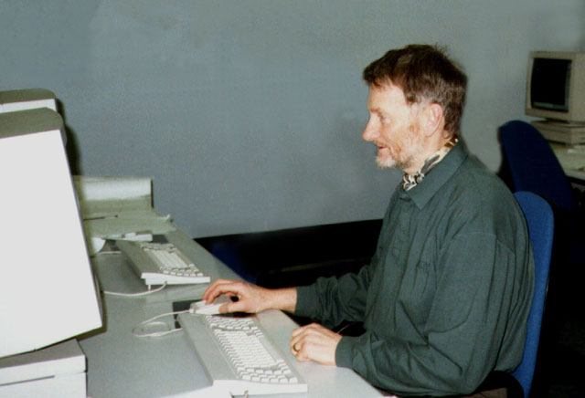
Working on the CAD computer, more or less where I ended up as the company, Leyland Product Developments, was nearing its demise.
I started in full time employment on 3rd September 1956. I was a Student Apprentice at Leyland Motoors Limited in Leyland, Lancashire. I was eighteen and 'wet behind the ears'. By lunchtime on the first day I thought 'What have I done?' It was such a come down. For weeks I had been vacillating between choosing to become a Teacher or an Engineer. Writing in 1999 I think, only think, I made the right decision. My 'education' at the 'University of Life' had begun.
This section is only an outline and needs rewriting - October 2009
Working on the CAD computer, more or less where I ended up as the company, Leyland Product Developments, was nearing its demise.
PROFESSIONAL REVIEW of the significant part of my working life.
All my experience has been in the Automotive Industry involved in the design of commercial vehicles. My early career was spent on transmission design initially working on the detail design of a range of heavy duty gearboxes and axles. In January 1966 I was promoted to Senior Designer going on to prepare original designs for two different new axles doing all the calculations, choosing the gear characteristics after research through papers, books and attending seminars etc..
In April 1969 I moved up into the Forward Projects Department as part of the team working on the new double deck bus (subject of IMechE paper 1978 Vol 192 No 7). I did the concept design of the new dropped centre rear axle, the design of the rear suspension and the independent front suspension structure.
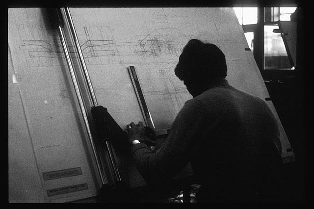
When we used to have to draw with pencils. This could have been the new double decker chassis?
In April 1974 I was promoted to Supervisor, Bus Structures, my first professional appointment, with three designers reporting to me. As a senior designer other designers had been assigned to me but this was the first time that I had had direct responsibility for the management and guidance of technical staff. I was responsible for all bus frames and mounts, including engine mountings and assisted in the introduction of computer and finite element analysis into chassis design.
In August 1977 I was promoted to Supervisor, Layouts and Structures, responsible for all bus layouts and structures with three senior engineers and twelve designers reporting to me. At this time I was becoming increasingly involved in human and industrial relations; interviewing, selection, training, development and promotion of staff and on one occasion organised the relocation of the department. In 1980 I was involved in the selection and purchase of Computervision Designer CAD equipment which we were to begin to exploit in my next position.
My next promotion was in December 1982 to Principal Engineer responsible for the design, test, development and introduction into production of our new worldwide city bus, the Lynx, subject of an IMechE paper (C205/86) by my colleague B S Hancock who was responsible for the body. I was responsible for the chassis (illustration 1) having about fifteen engineers / designers reporting to me plus the chassis engineering side of the new prototype department at Workington. We worked together with our teams reporting to our manager who reported to the Engineering Director. The manager took care of the interface between us and Sales and Marketing and customers at executive level, involving us when necessary and helping to present the new technologies we were proposing to the directors and at the same time making sure we kept to the project specification or negotiating any improvements we had designed or changes to targets that we could not realistically achieve. Creating the chassis frame was my major personal design contribution to the project and among my responsibilities in leading the design of the complete chassis were designing the space for all the units, services for the units (piping, wiring etc.), serviceability, accessability, correct environmental conditions for the units, weight, performance and manufacturability. At the start of the project we discussed with manufacturing the methods of manufacture that were available to us or that would be required. We visited likely suppliers, particularly the company that was to manufacture the frame components. I organised my staff to consult with the experts available to us within the company and outside eg legislation, ergonomics etc.. Some of our designers were either young engineers in their first appointment or designers inexperienced in chassis design. I allocated the work to suit their abilities and in such a way as they could develop as engineers and designers, using my knowledge of engineering and engineering principles. I planned the work so that the long lead time items were designed first and arranged for the ordering of all the material for prototype vehicles, spares and for use on the test rigs. Although we had a clean sheet of paper it was my responsibility to see that we made maximum use of existing components and not create any unnecessary new parts.
The Lynx frame is an all welded structure (illustration 2) a new departure for our company in this country. The frame was designed based on experience and knowledge gained on my earlier projects and making full use of the CAD equipment. The sections were initially chosen based on this experience and we did analysis work to prove them correct. Independent stress analysis by our colleagues showed that only minor adjustments to the design were necessary. I had to decide when the designs had reached the point where further work would yield little improvement on them, and for keeping within the target times for completion. At the time of prototype build I had to help the new prototype department to plan the stages of build, I was on the selection panel for the position of the engineer in charge at Workington.
| My finest hour at work. December 1983. The first prototype Leyland Lynx chassis outside the Prototype Department at Workington. | 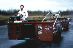 |
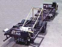 |
Later the same day, just before Christmas. The chassis in the Workington Test Workshop being prepared for shipment to Belfast for it's body to be fitted. I was to follow it in spring to supervise a few changes to the exhaust and inlet system to please the customers, Ulsterbus and Citybus. A week in Belfast with the 'Orangemen'. |
The first prototype arrived in Belfast on time. During this time I was involved with the sales and marketing of the bus and I spent some time with sales personnel, customers and the bodybuilders in Ulster and Perth Australia where the first two prototypes were respectively bodied. The Lynx is now established in the UK and is being considered for Europe. We have a demonstrator in Singapore creating interest in the Far East. We have had a few structural problems, sidemember crack and rear engine mounting crossmember failure, operating in Merthyr Tydfil but these have been satisfactorily resolved.
In September 1986 I was appointed to the position of Principal Engineer on Design Analysis, a new department developed out of the structures and materials department to bring together specialist knowledge and design experience to strengthen and broaden these into new fields and at the same time enabling fewer people to be employed in the area.
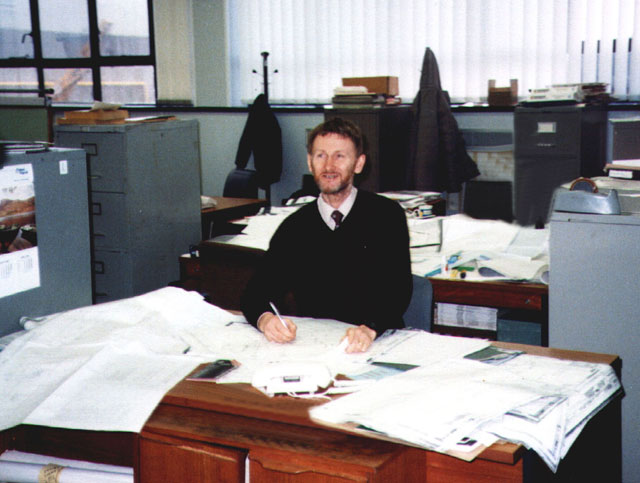
This was my desk when I worked on Design Analysis
The inspiration behind my appointment was that I would be able to use my knowledge and ability to filter engineering problems producing solutions relatively quickly and cheaply allowing us to concentrate our time on the difficult problems. I report direct to my chief engineer, who allocates my work and to whom I report work progress and completion, as one of the three principal engineers making up the department. There are about fifty engineers / designers who rely upon us for leadership and guidance on engineering problems, analysis, materials and in my case design. Our computer programs are supported by Istel and our own engineering services otherwise we are completely self reliant. My responsibilities include the leadership of the design of chassis frames and frame structures including in depth structural analysis, using the latest finite element techniques, and complete vehicle structural analysis. I apply scientific methods and outlook to the analysis and solution of engineering problems including original design and major service problems. I have to develop a thorough understanding of vehicle structures with special consideration to their influence on vehicle design. I am responsible for keeping abreast of new manufacturing methods and materials and to improve design and analysis methods through the creative use of new technology.
My first engineering problem in my new role was to fly out to Singapore to approve the fitment of a body, designed and manufactured in kit form in Scotland, onto the Olympian double deck chassis. In two weeks with the Singapore Bus Company's Engineers and a body Engineer from the Scottish bodybuilder I had to negotiate, as the Leyland Bus structural engineer, acceptable design compromises and convince the customer that the vehicle was structurally sound.
My next engineering problem was to analyse the design of a new heavy duty front axle beam. We have load conditions which have evolved over the years as have our methods of analysis and for a long time "belt and braces" designs have been created, but today we need to design to greater efficiency. I did my first serious structural analysis in the seventies on a rack and pinion steering gear using hand calculations. All my gear calculation previous to that time, although done by hand and involved, were following established procedures and the actual calculations did not require much intellectual effort. Since then from time to time I have been responsible for structural analysis but this was performed by the engineers and designers reporting to me. To bridge the gap I attended Nastran and Caeds courses at Istel so that I could combine my experience with the latest new technology and have continued to do so. The computer aided FE methods allow greater depth of investigation but they are not absolute. I took the existing beam and prepared a complex model (illustration 3). I used the knowledge of the use of the CV CAD design facility to prepare the geometry base of the model using the same data base that the designer had prepared transferring the model to the Istel Meteor system where we use Caeds and Nastran to do the analysis. This was another first for our company. Today my colleague has carried this further and we now prepare the finite element model on the CV system and write the Nastran file direct. I subjected it to all the known loads that are experienced in service. These loads are obtained by fitting transducers to existing vehicles. There was not time to do this so I had to research reports of previous tests. We had not the facilities to even subject the existing beam to simple deflection tests at the time so to proceed I had to make engineering judgements. Particular attention was paid to areas where the existing beam had failed. I prepared the new model (illustration 4) did the analysis comparing the results and proposed engineering changes or confirmed the design where it was acceptable to allow development of the design. We had to be right because we had to commit to production tooling to produce the prototype beams. I have colleagues to whom I can approach for information and discuss ideas with but at the end of the day it is my responsibility to provide design information. The axle, although not in series production yet, is successfully proceeding through the test programme.
In the spring of 1987 I was given my next engineering problem which was to design a chassis frame for a new concept of a minibus from a written specification and a thumbnail sketch. I produced a chassis frame design starting the iterative process of design - analysis - design etc., (illustration 5). The project was given to my Chief Engineer and we were assigned several inexperienced designers. I took over the design of the bus which fortunately coincided with an upgrade of our CAD designing facility which gave us the capability of user friendly 3D design. I organised the use of the system allocating layers to each designer's area of work and introduced them to 3D design. We kept a master scheme to control the project by renewing the layers when each designer made progress, my colleagues supplying us with expertise on suspensions, steering, brakes, power units and transmissions. The project almost collapsed because of transmission difficulties with drive angles making the costs unprofitable but over a weekend I was able to use the CAD technology to completely redesign the chassis layout and produced a totally new concept creating an acceptable proposal to put before the board (illustration 6). The board decided not to proceed with the project on economic grounds.
Recently I have been resolving two chassis structural problems (illustrations 7 & 8) and redesigning the floor of one of our buses to make it easier to manufacture. I am now working on the design of a new chassis frame.
The the type of work I did at this time was ranging from in depth structural analysis to the leadership of design in the resolving of mechanical engineering problems, to the training and development of engineers and designers.
I was soon to be required to take over the design of the new frame for the Volvo World Wide Low Floor City Bus, code named 5370. I wrote a paper on this project and it is substantially reproduced below.
THE DESIGN PROCESS Design is the process which starts when a need is recognised and finishes when the need is satisfied. On recognising the need the problem is defined and analyzed, a design produced, optimised, evaluated and finally introduced into production. Twenty years ago I stumbled across a textbook3 which confirmed the way that I had been doing things over the previous ten years and seeing my ideas in print it gave me the confidence to go on.
The NEED for a chassis frame normally arises out of the need for a new vehicle and is usually part of a major project. This comes about for a variety of reasons, market demands, legislation changes, rationalisation, cost reduction, re-sourcing, rarely for purely reasons of engineering excellence or the advancement of science, although this does not mean that this is not desirable or indeed should not be an aim.
The DEFINITION OF THE PROBLEM or specification is done by the board through marketing after consultation/discussions with all department heads and senior staff, the need may have been identified by any one of these. The specification is now described in words and the first stage of the design process is completed.
The SYNTHESIS begins with the concept stage when all avenues are explored within the initial specification. This can involve various positions and attitudes for the engine and other major units. The decision to make a whole vehicle or just a chassis may have been made earlier but will almost certainly be made by the end of this stage. Will there be a traditional frame, eg Volvo B10M, diagram 1, or Leyland Tiger, or just a basic structure eventually to be part of a complete vehicle, eg Leyland Lynx, diagram 2, or even a part structure, Dennis Javelin, diagram 3, or a complete vehicle structure, Mercedes Benz 405, diagram 4? Diagram 1 - Volvo B10M Diagram 2 - Leyland Lynx Diagram 3 - Dennis Javelin Diagram 4 - Mercedes Benz 405 At the end of the concept stage the vehicle layout will be decided and the frame philosophy outlined. Weight distribution, vehicle performance, likely cost, profitability and manufacturing sources will all be decided. Several mock-ups (design aids) may have been prepared to demonstrate the ideas. The engineers / designers will have prepared a report which illustrates the preferred design and explaining the reasons for this and explaining all the avenues explored and possibly suggesting alternative solutions for the board to consider and choose. Confirmation may be needed by the board before proceeding beyond this point. The serious design begins now leading to prototypes being built. The design team starts to draw in earnest and designs produced from which the individual designs and assemblies can be made. Each area is analyzed and optimised. Calculations are made and testing is initiated for those items or assemblies which are considered critical or where the designer is unsure of the performance of his design. Not all designs can be evaluated by calculations. Some components are so complex that it is still easier to evaluate them by testing. Testing will be required to correlate the calculations and confirm assumptions that have been made to have been able to do the calculations. A full size model, mock up or design aid will be constructed to confirm that the design will go together and this model is also used to tidy up areas too complex and time consuming to do any other way. It is remarkable that even with today's technology and design aids, solutions to problems occur in a flash once the real thing is presented to you even though you feel that you know every millimetre of it before hand, nevertheless I cannot help envying the young engineers of today who have so much computer power at their finger tips. Ideally the initial design is developed and analyzed, doubtful or high risk areas rig tested, eventually the design evolving and prototypes constructed for the final evaluation or sign off. From the concept stage onwards all the ideas will be analyzed and so the preliminary ANALYSIS begins at the start of the design. OPTIMISATION is taking place all the time, even outside working hours as the committed designer becomes so involved that his subconscious mind continues when he breaks off formal study, often the solutions to his problems occur during this time, Archimedes being an early example.
The whole procedure of SYNTHESIS / ANALYSIS / OPTIMISATION continues as an iterative process until the designer achieves his objectives. The secret of all good design it to know when optimisation has to stop, when the return for time spent is minimal compared with the targets already achieved. Nothing is ever perfect and every design can be improved ad infinitum, but freezing the design at the right moment is the secret of commercial success. Every designer has to control the urge to make changes once this point has been reached. From this point all new ideas and solutions have to be recorded for consideration for mark two of the product. Many companies overlook this mine of information, this familiarity with the project, and neglect the development of the product once it is introduced into the market place, relying on "fire fighting" and customer lead developments, wasting precious hard earned knowledge. It is a sad fact that continuity is often only paid lip service. Many design teams are allowed to break up or are indeed broken up by the company at what is perceived as the end of the design process.
When a new project is needed a new design team is set up or a new contract design company brought in. Diagram 5 - The Stages of Design showing the iterative process EVALUATION begins with the first design and continues through the analysis and optimisation phases. Final evaluation begins when the design is frozen and the production designs and specifications are prepared alongside the testing and are ready for issuing at the end of the evaluation / confirmation period. This then is the design process illustrated in diagram 5, previous page. An approximate time scale is shown in diagram 6 below Diagram 6 - Approximate Project Time Scale
CHASSIS FRAME - DEFINITION What is a chassis frame and what is it's purpose? The ideal bus/coach is one in which all the vehicle is devoted to passenger space, ie the more passengers the more revenue the better the accommodation the more attractive or satisfactory the vehicle is. The ideal vehicle is a box, the entire floor dedicated to passenger seats or standee areas. The closest we get to this is a railway carriage. However even a railway carriage needs an engine. To move the bus needs wheels and some of the wheels need to be driven, normally through the rear wheels and others, usually the front, steered, that is, used for guidance purposes. The driver has to be accommodated and all his controls including steering. Mechanisms have to be carried to steer the vehicle. The wheels are fixed to the vehicle via the suspension. The suspension supports the vehicle and the passengers on the wheels. Through the suspension come all the road surface loads due to the vehicle moving, the cornering forces, the drive and accelerating forces and the deceleration forces through the brakes. The engine, gearbox and driveline and all the systems have to be catered for. The engine has to be fed and it's waste products dealt with. It has to be kept at the right temperature and the vehicle protected from it's waste heat. Ideally the complete vehicle structure is designed to accommodate all these loads and considerations but practically at this point in our history it is politically expedient to produce a vehicle chassis with a frame performing as many of these functions as possible. To carry the passengers, driver and all the units we need some form of structure, ideally a complete body/chassis, an integral vehicle. This structure needs to be capable of carrying all the passenger loads, all the units, eg. engine, gearbox etc. and absorbing all the dynamic forces associated with moving a mass along less than perfect road surfaces. Therefore the chassis frame's purpose is to hold all these units in position and absorb all the loads whilst protecting and delivering the passengers. It is possible to design a frame to do this but this places an unreasonable demand on the vehicle if it is to be anything other than a truck with a high platform passenger area. (This is still the cheapest way of transporting people or cattle). So additional to the above considerations a modern frame must be capable of integration into a complete vehicle channelling all these forces into the eventual body structure.
DISCUSSION ON PRINCIPLES In vehicle design the frame is not an end in itself but a means to an end. Compared with the power unit it is relatively simple or, complicated within a narrower sphere than the fields of design of an engine. It is much larger in size but can be smaller in terms of dedicated investment, or is it? For a given power requirement it is possible to use a power unit that is used for other applications, this needs an explanation. Bus manufacture has developed on the back of truck manufacture. The flexibility of a truck or a lorry compared to a railway wagon and it's power and speed compared to a horse and cart has lead to it's desirability as a means of transporting goods and the numbers have reached quantities that justify investment in tooling. With all the major components available in series production for trucks it follows that buses can be made utilising these components relatively easily. The first buses were built on to truck chassis, enabling the whole of the truck to be utilised but with the growth of public transport there was a demand for a bus that was easier to get into and out of which was translated into a lower floor (the railways built platforms) which lead to special frames being designed to permit this. Generally the frame is the major difference between a truck and a bus but it can now be said that with the increased time spent on bus design the situation has reversed and this has lead to many developments on buses being fitted to trucks. However the bus industry still relies on the truck industry purchasing power to supply it with units. It follows then that the frame is to a large extent considered secondary to the other major units such as engine, gearbox, axles and brakes, wheels and tyres. Nevertheless the frame is the major unit in terms of innovation in the bus industry albeit the least glamorous and on the face of it the most crude and therefore perhaps the least understood. Colin Chapman of Lotus fame is reputed to have said many times when designing car chassis frames that "I do not know why, but do it that way as I know that is right" or similar words expressing that sentiment. One of the first considerations is the passengers and, perhaps a contradiction, squeezing as many as possible into as small a space as possible. The units are placed according to weight distribution, effectiveness and minimum intrusion into the passenger space, similarly the axles and wheel housings. Consequently there is usually no room left for the frame which has then to hold them all in position until a body is fitted. It is essential that consideration is given to all the ways in which the frame structure is loaded. Once the vehicle layout is decided the design of the frame structure will be influenced by the loads that it is required to carry or absorb. Brackets for mounting systems etc need integrating into the frame. In the sort of vehicle that we are talking about the stiffness of the frame will be small compared with that of the body. Although the individual body components at first glance may seem to be weak and flexible, as a whole they are considerably stronger than the frame. If you press hard on the side of a bus, or a car for that matter, you should be able to produce a dent so how can something so weak carry the weight of an engine and gearbox unit, in our case around 1500 kg.? The frame has to be designed so that the loads it carries can in part be absorbed by that very weak and flexible panel. This principle applies to all units and components fitted to the frame. The suspension for instance absorbs the load from supporting the bus, from bumping up kerbs or down pot holes, cornering and braking as well as accidents. If you get hold of your car aerial and pull it at right angles to itself it invariably snaps off. This is because it is relatively very weak in that direction compared to the body side to which it is fastened. It is not designed to withstand those loads because, car washes excepted, it will not be subjected to them. Another consideration is that during accidental damage it is ecologically sound to sacrifice relatively cheap and easily repaired components, for example it is simpler to replace the aerial than to repair or replace a body panel. Each component of the frame must be designed to carry the loads it will be subjected to and also a "pecking order" has to be established for sacrificial components. The power unit is normally mounted on three flexible mounts. These mounts are designed to protect the power unit from the structural loads of the vehicle and the dynamic loads from the vehicle suspension. They also have to isolate the engine vibrations from the structure. Engine mounting design theory relies on being mounted on a relatively very stiff and heavy structure so the frame designer has to provide as stiff a structure as possible and as relatively heavy as possible. If you look at the second moment of area of a 300 mm desk ruler you can see that it is dramatically more flexible when it's cross section is horizontal and much less strong in bending. You only need to pick it up and play with it for this to become obvious and to realise how easy it is to break bending it one way and almost impossible the other. It is necessary to be able to "feel" how a component behaves to be able to use it correctly in it's correct attitude and be aware if it is suitable. There is a much quoted saying "if it looks right it is right" but to whom? Perhaps an artist, as a perceived non-engineer can do this but as well as being a gift this art can only be acquired by a thorough understanding of structures. If you look at a tree you can begin to understand structures. It's tiny flexible easily crushed leaves are strong enough to gather the power of a storm force wind and snap it's trunk like matchwood, the leaves do not come off (except in autumn of course), a trunk big enough to support bridges, railways and hold a boat together in the wildest sea. Look how the slender stem of the leaf gets thicker as it joins the twig and likewise as the twig becomes a branch and the branch joins the trunk and then how the trunk has large roots to anchor it which become similarly progressively smaller down to their extremities. The loads in the frame have to be similarly absorbed, transferred and dispersed. In designing a structure all transformations and joints must have a gradual change in size, if you look around you will see countless examples and when you begin to understand the ones that survive you will be on the way to feeling "if it looks right it is right". If you design a welded joint of two 10 mm thick plates with a 5 mm fillet weld they will easily snap off, if you join a 5 mm plate to a 10 mm plate then the 5 mm plate will break. Even the tree is not perfect because if you get hold of a twig and bend, it breaks off at the joint where it meets the thicker branch. Obviously you cannot do everything as I have suggested but you need to understand the potential weakness that you are creating and indeed even exploit them as in the case of the car radio aerial. Manufacturing methods, tooling levels and finished requirements, eg CKD etc. are a very serious design consideration. Even the first ever frame, designed on a "clean" sheet of paper, had to consider the tools and materials available for its manufacture. There are circumstances when it is recognised that a new product can justify a completely new manufacturing facility, one example of this in the early seventies was the Leyland National Bus plant in Cumbria set up with government funding. Today there are new facilities springing up all over the world but whilst some of these are new custom built facilities many of them are just copies of current production units resited for political and commercial reasons. In the world of bus frames the industry is still too fragmented to allow a major investment in frame manufacturing facilities. If buses are to compete as anything other than a social service then contracting or rationalisation of the production facilities will have to occur to justify the massive investment that will be required to produce buses on the same scale as passenger cars. Examples of this sort of investment in frame manufacture are the Range Rover and the Vauxhall Frontera made at Thompson's Motor Pressings. Consideration will have to be given to the basic construction of the frame. Is it to have continuous longitudinals or continuous crossmembers. Can these members be pressings or rolled members eg channel sections. If the shape is too complex to be a parallel member can it be formed or must it be pressed? Can it be cold rolled or will it have to be hot rolled? Can it be cold formed or does it need to be hot pressed? Have you got the facilities available to produce a hot pressed sidemember 12 metres long? Has anybody got the facilities to produce a hot formed 12 metre sidemember? Have you got access to facilities to press small components to produce a welded assembly? Is there space enough for a full load bearing frame or is there only sufficient space left for connecting members? Will a space frame be more efficient? Are you designing a complete vehicle or will you have to cater for local bodybuilders? Is your bodybuilder capable of designing a body to integrate with your frame or must you design a body structure for them? Must you allow the bodybuilder to weld to your frame, to drill holes in your frame, cut holes in your frame or even lengthen or shorten your frame. The questions relating to manufacture are many, varied and complex. Volvo purchase frame sidemembers from Japan for vehicle manufacture in Sweden so you can see that the problem is a global one, embracing the entire world. The frame may need to be self supporting and/or capable of taking the complete vehicle loads similar to a truck frame. The political situation in the bus and coach market is such that the operators want to fit a locally constructed body which can also be customised to their own requirements.
DESIGN OF A BUS CHASSIS FRAME A frame is required to be the basic support structure for a new low floor city bus. It is part of the need to produce a new advanced vehicle to maintain the company's position in the market place and to break into new markets to ensure the survival of the company in order to be able to maintain an acceptable and improving return on the capital employed. To fulfil this need the product must in turn satisfy the needs of the customer. The frame is defined by the floor height (hence top of frame), the approach angle, the ground clearance and the departure angle which have set the basic envelope available for the frame. The floor height was chosen to compete with other manufacturers' vehicle layouts to provide an even lower boarding step to make it easier to get on the bus and further to have no more steps for the main area of the bus. The entrance to the vehicle has to be capable of accepting a wheelchair lift. The width over the front axle is determined by the front suspension but the front suspension had to be designed in conjunction with the frame to allow a wheelchair to pass through easily. The dimension across the central sidemembers comes again from having to cater for a wheelchair lift on the central door but may also be influenced by the maximum gangway width compatible with getting some structure over the rear axle. Bay widths were selected to suit the recently introduced highly tooled RVI 312 body, as it was a requirement that the frame should be capable of taking this body whose design was fixed by virtue of it's tooling. A paper was put to the board at the end of the concept stage, part of which was a section17 which described the frame. The vehicle layout having been decided and manufacturing methods considered targets were set for the frame, eg weight, cost stiffness, strength. Our targets were the vehicle targets to Volvo Functional Requirements18 with specific targets: the life of the frame is to be the life of the vehicle; in this period no failures are to be allowed and no maintenance should be necessary; it must be possible to repair accidental damage; 30 mm maximum vertical deflection at 3g bump load - later revised to 15 mm; there was to be minimum Tooling Investment. Brackets welded or bolted to frame attaching components or units would be designed by the relevant unit area but would be done in conjunction with the frame team. Frame team would redesign brackets if necessary to protect frame. The initial weight distribution calculations were completed. Spreadsheets are useful for this. The object is to find the fore and aft distribution to ascertain that the axle loads are practical and within the law and also that tyres and wheels with sufficient capacity are available. With all this information it was possible for me to construct bending moment and shear force diagrams adapting the above spread sheet and illustrated in diagram 7. These are very basic but at this stage give an overall picture for little time and effort. This gave an indication of the relative strengths required and is the basis for serious design work on the frame to begin. It was now possible to make the first estimate of the size of the main members. These calculations13 were done by hand but it is much quicker and more consistent to create computer programmes to perform these tasks on personal computers which are available in design offices. We were now in a position to produce concept schemes exploring the design possibilities for analysis and evaluation. Further to this we needed to get a complete picture of all the forces and stiffnesses that we needed to cater for to be aware of the overall design requirements but at this stage as long as we have these loads in our mind we are able to proceed considering the vertical loads only and we use the maximum probable load which we have found to be 3g or three times the static load from experimental work done over the years. 7.1 - Spread Sheet 7.2 - Shear Force 7.3 - Bending Moment Diagram 7 - Vehicle Weight Distribution, Bending Moment and Shear Force Spreadsheet (Excel) We have discovered that the maximum load is 1g, ie static, plus or minus 2g giving a load range of -1g (rebound) to 3g (bump) that is a 4g range overall. To allow for fatigue we have also determined empirically and from S-N curves that if we keep the maximum stresses calculated below 75% of the material's yield strength that we will have no problems. Experience has shown that if vertical loads are considered and solutions found for them at this stage that the sections chosen can usually cope with the cornering and braking loads. We have an idea of the space available for the material sections and of the manufacturing techniques that we will be able to use so we can begin the outline design choosing the sizes appropriate to the rough calculations13. f/y = M/I = E/R is the basic relationship on which all our early calculations are based. All the relationships between stresses etc and the various load cases can be found in Roark 4. Most steel manufacturers supply catalogues which give you all the material and physical properties that you need and lots of useful information about structural sections. A typical example is British Steel's Leaflet 5. You can use standard structural sections, circular, square or rectangular hollow sections, rolled channel sections, formed channel sections, pressed sections and any combinations that are correct for your particular design. In considering the basic sections that you are going to use you need to think about lateral and torsional stability. For bending strength you need to design or use a section that has most of it's material on the extreme fibres, for vertical bending this is the top and bottom flanges. Ideally you want a channel with thick flanges and for strength you can manage with a thinner web. It is important to consider the stability of the section, that is, it is no use having a section which is theoretically strong in bending if it has too wide flanges which will be unstable so there is a relationship between flange width and web depth which has to be satisfied to prevent your flanges collapsing or buckling. If you use an open channel section you need to ensure that it is supported so that it is stable under lateral loading and ensure that it's vertical loads are applied through it's flexural centre otherwise it will just twist and collapse. You will need to find some other way of controlling torsional loads. Rectangular hollow sections are a logical choice for chassis frame members but there is not always room to fit them, as in this case, as they are only produced in a range of proportional sizes, always being at their narrowest no less than half the depth. Over axles, particularly rear axles on a rear engined bus, you have to cope with large vertical loads but to leave space for a gangway between the wheels you are often only left with about 50 to 60 millimetres for the width of your frame longitudinal members. It is therefore necessary to fabricate a section if you need to have torsional stiffness at this point, which indeed you invariably do. The simplest way is to take a formed channel and weld in a straight flitch. This channel will invariably be shaped to pass over the axle, diagram 8.1, so you will need to have the channel pressed into shape which requires tooling and hence high volumes for a return on the tooling. An alternate method is a fabrication of formed sections , diagram 8.2, another way is formed tubes with shear plates welded either side, diagram 8.3, or a space frame, diagram 8.4 or a combination of both, diagram 8.5. If necessary we can have sections of the frame made and tested to analyze their behaviour but with the advances in CAE we can build and test various ideas on the computer without cutting any material and obviously saving months of time. The front10 and rear11 wheelarches are examples of this. We have a low floor vehicle and need a wide gangway over the front suspension and we have very little depth to give us strength so we had to consider structural wheelarches to get the suspension loads into the sides of the body. After the initial synthesis we made two simple cardboard models of a spherical wheelarch and a cylindrical one. It is perhaps obvious that a spherical one is better than a cylindrical one but we did this to justify the choice of a spherical one to the project leader. We also prepared simple FE models of the two shapes and as anticipated the spherical one was found to be twice as strong. Visual aids are worth more than any amount of words especially when there are several different languages in use. We visited manufacturers, PolarCold and Ewarts. We got an estimate for a spherical wheelarch as a pressing but the tooling costs were totally out of the question for our project. The final design was achieved after full co-operation with the manufacturer, we were surprised to find that we had introduced difficulties trying to make it easier to make, so we were pleased with the final outcome although as usual we could have gone on improving it. With this in mind we evolved a design of wheelarch compatible with our minimum tooling allowance, ie it could be made with simple folds. At this stage we prepared an FE model of the frame from the front to immediately in front of the rear axle using our Stresslab facility on our CAD system and passed it to RVI for analysis, RVI up to this time were designing the rear end of the vehicle and it had been agreed that they would do the overall vehicle FE analysis. I was made responsible for all the project calculations and had an opposite number at RVI in Lyon. They reported that the design was okay but no evidence was produced as we lost contact with RVI soon afterwards, see below, but their communication gave us the confidence to proceed with the design and our own calculations. Our previous suppliers, our Workington plant, Thompson's and Ewarts, being the nearest geographically were consulted and had foreseen no problems for their facilities but then the nominated frame manufacturer highlighted difficulties that his company may have encountered with the proposed rear frame design. It was then necessary to do an investigation into the possibilities of reducing the complexity of the design and hence reduce the cost of the rear wheel area before completing the detail drawings prior to the re-building of the mock up under construction. A paper12 was presented to the Project Leader, Frame Manufacturers and Volvo Design Analysis to facilitate the joint seminar to resolve the company problem. This illustrates the importance of considering production facilities. It is interesting to note that the circumstances can change during the design process. The initial project, from which early studies were done was cancelled with the merger of Volvo and RVI, ie. RVI already had a product which catered for the bulk of the requirements of this design. The second phase, a joint project was cancelled because it was felt that the markets being catered for were sufficiently diverse for two versions of the bus to be produced (that story is much simplified). At a later stage the circumstances changed because the board were becoming sufficiently impressed with the progress of the design that they were prepared to make more money available to use sophisticated pressings if they could reduce the cost of the product. This product is to fill a gap in our product range that other manufacturers were satisfying which could lead to us loosing sales in the city bus markets. We were therefore already behind. To change to pressings at this stage would have added six months to the design time and then added six months to the procurement of tools delaying the introduction of the vehicle by a year by which time we could be out of the market and out of work, therefore the possible cost benefit was abandoned to be introduced at a later date once the product had become established in the market place. An investigation11 was necessary to convince ourselves and our leaders that we had chosen the best arrangement of our design. Diagram 9 shows one of the deformed geometry stress plots from the analysis. Another surprising revelation at this stage was that pressings in the form of welded assemblies, diagram 8.2, which had been considered right at the very beginning but space could not be found to fit them in, now appeared possible (an example of the iterative design process). The problem was so complex at the rear behind the rear axle that I had made the decision to design a floor structure that would be capable of doing the work of the frame as described above. The units had been positioned to give the maximum possible floor space and seating arrangements so the floor had been clearly defined. Diagram 9 - Deformed geometry plot from one of the rear sidemember possibilities We used rectangular hollow sections with shear plates. It was only after the evolution of the design of this tubular/shear panel frame that paths for channel pressings were found. It was not quite as simple as that though because it would have been more difficult to integrate the pressings into an efficient structure, hence the six months extra design work required. This was a time when the pursuit of excellence had to give way to commercial considerations. The design of the rear end was approached from the point of view of the completed vehicle, we used what would have been the floor structure, traditionally part of the body and bodybuilders' responsibility, to be the "frame" and indeed we used a lot of the floor itself by designing in 3 mm thick steel plates. This gave us a depth advantage as we were able to reduce the thickness of the traditional plywood floor down to the 3 mm steel. The steel plates gave the added advantage of being fire barriers and sound barriers, an example of this is the contribution that I made to the resolution of the Leyland Lynx noise problem when I redesigned the rear body floor structure, see IMechE Paper 6. The cost and weight advantages are obvious and on the face of it the only way to go, but this is not the case in the real world. Firstly we have to compete in the market for selling chassis so if our chassis costs more than a competitor's we lose out at the first hurdle. If we include body structure and floor that will make the body cheaper surely? No I am afraid not. Illogical as it sounds if the chassis manufacturer includes body structure it does not reduce the cost of the body, it simply increases the profitability of the bodybuilder. Sadly we were surprised to learn from our design auditors in Volvo that we gave too much consideration to the vehicle as a whole. Our brief was to design a chassis so the rear end was amended to reduce the cost of the chassis. At this stage the vehicle assembly team were our constant companions and various compromises were agreed to make it easier for them to put the bus together. I believe that the modern buzz word for this is "simultaneous engineering". I cannot understand why people get excited about these things because I have always tried to work this way. The designer considers the vehicle performance and its service requirements, that is the vehicle as it is perceived by the customer but if these are his only considerations he is likely to come unstuck. The method of manufacture has been stressed above but you must also consider the frame and it's relationship to the production line. The initial concept of the frame was based on our knowledge of our production facilities. We had agreed revolving welding jigs so our initial design considered this and our floor plates were acceptable as the frame could be turned over to weld and all areas were accessible for welding. Service attention was considered, access to units, removal of engine, gearbox etc. - no problems. Our service target assumes all service has to be done from the outside of the saloon. The original assumed production facility was organised round a high lift and all units were raised on special trolley lifts and fitted from underneath so we appeared to be well on the way to success. However when the actual production facility was identified or to some extent better understood we found that our liberal use of floor plates to strengthen the frame was causing embarrassment to the plant which would do the final assembly of the chassis. They used the docking system with the chassis at operating height and all units had to be fitted from the top once the frame has been lowered onto the major units which were then to be craned into place. Many of our floor plates prevented access for this so further design development took place. Once the structure was refined to overcome this and also reduce the complexity of the "integrated" rear end and hence become easier to manufacture and therefore significantly reduce the cost of the frame, further studies by the vehicle assembly team requested modifications to permit the use of their existing procedures without any change to suit the new chassis. (It is interesting to note that the Swedish company are more concerned for the environment of their workforce than we had tended to be, although we would have been horrified if you had accused us of this). Any doubts that anyone may have had about constructing full sized mock ups were by now dispelled, although it must be stated that with the CAE facilities now available this should not be the case. It will be interesting to consider the cost of the mock-up against the cost of additional engineers needed to use the new technology to the full to replace the mock-ups. At this point the vehicle was fairly well described by our working schemes and many detail drawings but even so many of the people both outside and inside the vehicle design team had not understood what the chassis was going to look like until they had actually seen it "in the flesh" so to speak. I should perhaps point out that within the vehicle design team we work to a very strict discipline in the way we produce our schemes. All schemes are drawn on the CAD system to a common vehicle datum. Our CAD system allows each designer to work in his own scheme but call into view the other designers' schemes in the background so that all of the time we are aware of each other's developments and problems. We have evolved a method whereby we chose a datum in front of the bus and below the bus. To always have datum x = 0 in front of the bus we place the front axle on datum x = 3000 millimetres. Because tyre sizes vary, even on the same vehicle, we place the wheel centres, note not king pin centres, on datum z = 1000. We have constant ride high vehicles so everything on the vehicle is nominally fixed relative to the wheel centre. The side to side datum y = 0 is on the longitudinal vehicle centre line. See diagram 10. Datums have been used since the first vehicle and our system is unremarkably simple but then so is the wheel. Utilising available technology is what I claim credit for and hopefully using it to its' best advantage, I cannot believe the difficulties I have had getting chartered engineers Diagram 10 - CAD Datums above, at and below my peer level to accept these disciplines and see the benefits that the technologies that we have can give, no doubt I have my own blind spots which you will point out to me. There are two types of engineer. There are those who, full of confidence, breeze on and never look back sometimes leaving a trail of disaster behind them and there are those who, early on, realise how little they know and with each discovery realise how humble they are, actually there is only one kind of engineer. Throughout this design project I have lead a team of inexperienced engineers of varying ability, all of them growing in stature with the project. If I could explain how I do this I could no doubt make a fortune but all I seem to do is get harangued for pushing back the frontiers of using new technology and allowing engineers to develop (I will admit that being lazy helps but so would Watt). I suppose I only get away with it because my results defend me. Using these datums each designer can work in their own area and by virtue of our CAD system can have all the other designers' schemes in the background on his or her screen. We work in 3D and increasingly in solid geometry. There is no apparent reason why we cannot manage without a full size mock up as the software is good enough and accurate enough to show us everything but the fact remains because our of our varying abilities there appears to be no substitute for a full sized design aid. We use Computervision CADDS 4 software and the facilities of their system are well known. To get back to the project, again, because it would have taken time to investigate these improvements, a decision was taken to proceed without further change to enable progress to be made towards the introduction date. It was possible for me to see at this point that there was a chance that the production requests could have been met without loss of strength and integrity with a chance of an even better frame but this had to be ignored to push towards the construction of the first evaluation vehicle. We now had the specification clear and were able to proceed with formalising the design proper. It was now possible to idealise the frame structure into a fairly accurate mathematical model and begin the preliminary stages of the overall structural analysis using finite element techniques. If we have done our initial investigative calculations sensibly we should already have sections of the frame modelled and able to be incorporated into our full scale model. Both the above examples10 & 11 were able to be incorporated into the final model. The density of some of the elements was modified to allow for the non-structural mass of the body. Up to now we have left the glass (windows) out of the model, knowing that it makes a significant contribution but not having time to incorporate the suggestions in the work by H. J. Beermann7. The analysis is used to evaluate whether we are achieving our design targets and test possible improvements. In the example we are using, one of our targets was that the overall vehicle deflection had to be no greater than 30 mm under a 3g vertical load. The analysis was run and the results scanned for the maximum deflection and pictures of the deformed shape used to try to understand what was happening under the loading conditions. At the same time the results were interrogated for stresses over the 75% of material yield stress. Obvious deficiencies were remedied and more difficult or unexpected ones were investigated in more depth to find the reasons or produce a solution. For example the original design of rear suspension outrigger was found to deflect rather more than desired and parts of them were above our stress limit for fatigue, I had felt that they were underdesigned but to encourage the designer I had allowed the work to proceed as part of his development. The area in front of the rear axle is the highest loaded in bending, that is it is the point of maximum bending moment under a 3g load. If you look at the frame you will see that this is the weakest point, it both looks wrong and, at the highest bending moment has the lowest elastic modulus. It may be of interest to know that the service personnel identified the outriggers as being in their opinion too weak, without access to our calculations, but fortunately for, us after we had changed them, so we were able to restore their confidence by explaining our changes. This again illustrates the importance of the involvement of all the parts of the company simultaneously but even more importantly the designers being prepared to listen and to justify their actions, maintaining the confidence of all the people involved is of vital importance for the success of the project. We did an experiment in the FE model disconnecting the supports from the front crossmember / outriggers to the frame longitudinals. This put more load into the outriggers and increased the deflection further. I was surprised that the "weak" centre section was contributing so much to the overall strength of the frame. We modified the model by creating an approximate section (in this case a rectangular hollow section 80 mm wide by 160 mm deep and 5 mm thick) for the outriggers and ran the analysis again. This produced a significant improvement in the overall deflection of the vehicle, so we proceeded to redesign the outriggers with this in mind, the actual properties of the section being corrected later in the analysis as the design evolved. The full load cases that we subjected the model to were 1g +/- 2g vertical - to simulate dynamic loads, 1g vertical + 0,8g longitudinal - to simulate braking 1g vertical +/- 0,8g lateral - to simulate cornering 1g vertical with one front wheel unsupported - to simulate one wheel bump 2g vertical +/- 0,5g lateral +/- 0,35g longitudinal - for lift and tow Round about this time there was emerging the belief that perhaps the frame should be made in three modules. It had naturally evolved into three distinct parts, front, centre and rear. The flexibility of the centre section, because of the limited space available it only had a depth of 100 mm, was causing concern amongst the manufacturing people. Transportation during manufacture and from the supplier to the assembly line was a problem. This could be overcome by fitting the transportation frame, a structure which would be necessary once the chassis was built up to enable it to be tested and manoeuvred round the plant and to and around the bodybuilders and at the frame manufacturer's, however the possibilities offered by splitting the frame into three were becoming attractive. It would be a lot easier to handle at all stages for everyone, welding, corrosion protection, storage, assembling as a chassis and transporting when complete, ie it could be assembled as three "plug in" modules. Several bodybuilders were known to prefer having only the front and rear modules leaving them complete freedom with the centre of the vehicle so it would be attractive to them. Both our nominated bodybuilders agreed although both of them elected to take the complete frame for the prototypes. It has become Volvo's custom to supply a short wheelbase chassis allowing the bodybuilder to cut the sidemembers and extend them by fitting structure in between. This had developed from the fact that most of Volvo's business is exporting and the reduction in length of the units saved considerable amounts in shipping costs around the world. We had a problem with a short wheelbase because most of our weight was behind the rear axle, our front wheels would almost lift off the ground, we had a chassis capable of doing wheelies. The chassis needs to be tested on a rolling road so we had to find a way of making it suitable in short wheelbase form of keeping it's wheels on the dynamometer. This will be done by putting a weight over the front axle for the purposes of the test. Volvo had just designed a clamping arrangement for the dynamometer for a rear chassis they had just introduced into production which clamped on the wheels. Our chassis would have structural wheelarches which would prevent this being used but it should be possible to amend the rig during trials. The quick "back of a cigarette packet" investigation into the design of the bolted joints showed that it was possible to have some of the bolts in the same position across and up the frame so it would be possible to bolt the two halves together for assembly or shipping however this gave a wheelbase of just over 1.5 metres which was considered too short, the optimum wheelbase for the chassis having been considered and found to be 3 metres by the chassis assembly plant. Two solutions then presented themselves, a reusable combined transportation jig and centre section, and a short wheelbase centre section that could be adapted for length by the bodybuilder. The reusable centre section was chosen, but has not yet been designed. The calculation14 for the front bolted joint was done using the information from the early bending moment diagram but the rear calculations15 were done using loading information taken from the FE model. Then, six months later, a further suggestion from the assembly plant was that they could do without the rear joint between the centre section and the rear module. This would simplify the design and consequently save costs but however attractive this development was we could not give up the time necessary to change all the designs without delaying our introduction date which as has been said before is very important. However with a bit of brilliant manipulation of work and work schedules we were able to introduce this. Further we added some body structure for the ramped floor, which was able to be removed by the bodybuilder for the flat floor, which made the addition of a temporary structure unnecessary. A quick calculation was done, diagram 11, and confirmed that this was practical, the BM calculations were adapted for the shorter wheelbase. A detailed FE analysis23 was done at a later date to prove that we had made the right decision, the initial calculations being vindicated, however crude. The full analysis22 can be used to identify and specify the body requirements and the necessary targets listed for the bodybuilder. At this stage the bodybuilder may not have been nominated or identified for confidential and commercial reasons so the designer has to make an approximation of the body from the market information in the vehicle outline description. In our example a body model created for a previous project was used, this model itself having been created from a prior investigation. Once the model is "running" satisfactorily the body can be strengthened or weakened as necessary. Diagrams 12 (body) & 13 (chassis) illustrate the fairly developed design model. Diagram 14 shows the deflection under the 3g vertical load. These illustrations can be enlarged to examine each area more thoroughly. Diagram 15 shows the stresses in the frame beam elements and diagrams 16 & 17 show the stresses in the chassis shell elements. Diagram 18 shows the stresses in the body beam elements. The FE model has given an overall picture but discrete areas will need further analysis. The model because of it's size is relatively crude so the areas where the suspension loads are absorbed will need a more thorough investigation. This can be done by creating very refined models of small sections of the frame using the boundary conditions from the overall model. Hand calculations can also be used for in depth investigations. An example of this is the rear suspension locating link mounting points, diagrams 19 & 20 show examples of the stresses in one of the brackets before and after modification. All welded joints which at this stage of our expertise are not modelled will have to be scrutinised and the appropriate stress factors used to assess the suitability of the joint. We have assumed that the stress at the joint is the stress at the toe of the weld. Using the appropriate weld classification21 in time we will be able to check each weld thoroughly although our experience shows that this is a conservative approach. We have used relatively thick tubes to give us stiffness and this has resulted in low stresses and also given us plenty of weld at the joints. Our findings will also help us to specify welding techniques and standards of workmanship required for all areas especially the ones that we have identified as critical. This is vital because this is where the cost of the frame can become relatively astronomical if we insist on unrealistic targets. Volvo has very clearly designed load conditions16 to be considered in all design evaluations and these have to be satisfied before the vehicle can be signed off.
EVALUATION At the end of the concept stage the evaluation necessary will be broadly evident. The number of prototypes desired will have been identified and the actual number, which will undoubtably be much less, will have been agreed. The urgency of the project will influence the use to which the prototypes are put and the selection of which prototype for which test. Ideally the first prototype will not be the one used for structural evaluation but in the case of our example the first prototype is the endurance vehicle because the vehicle will be a late entrant into the market as explained before. (The overall vehicle will have a number of firsts so it will have attractive selling features that are ahead of the market). Therefore the structural design must be finalised before the first prototype is started. It will not be but by the time the first prototype leaves the workshop it will be to the latest design. The object of evaluation is to prove your design, not only to show it's strengths but to show up any weaknesses. The designer will be bonded to the design he has conceived like a parent to a child but he or she must leave all family prejudice behind and be objective. He or she must be completely impartial, possible weaknesses must not be nursed through obligatory evaluation tests, this may not be easy because your career or livelihood is at stake, doctors bury their mistakes we have to live with them8. It is very hard in our society to do this because, as I believed when I left school, it is not sufficient just to work hard conscientiously and competently, even brilliantly. They say cream always rises to the top but also so does the scum. Similarly during the design process do not be blinded by your loyalty and belief in your creation, your colleagues and team will be able to contribute to the project, will be able to spot the flaws in your design, will be able to carry an idea further when you may be tired. Before the final evaluation, in our case the endurance test, many other tests will have taken place to test components, new ideas, new materials and new combinations hitherto not used. Bolted joints need vibration testing. Complex welded joints need fatigue testing. Joints need stiffness evaluation. Computer simulated test need confirmation. All these must be planned by the end of the concept stage. Service engineers must be given the chance to audit the design to see that their requirements in the initial specification have been met. Is it possible to get a jack under the frame to change a punctured tyre? Can you change a fuel injector? Production engineers must be consulted at all stages to ensure that their requirements are met. Can the engine be installed with the gearbox and propshaft having been assembled together and torqued up off the main line? Quality targets need to be evaluated. A series of "quality gates"19 must be "passed through" to achieve these targets. Functional targets need to be evaluated. All these need doing before the final test takes place. The final test should confirm all your decisions not highlight areas for development, if it does the latter you have failed. Volvo Bus Corporation have developed an endurance test20 which is an integrated accelerated life test which experience has shown to show up weaknesses. The frame used as our example is part of a vehicle which utilises a new independent front suspension. This suspension produced some challenging problems to the frame designer. The solutions to these problems ideally need to be evaluated before the first prototype is built and to this end an existing vehicle was converted to take the front suspension to undergo an accelerated life test (1600 kilometres at the MIRA pavé proving ground). This test is a bit expensive for a frame evaluation alone but as it was necessary for the new suspension we were fortunate to be able to "ride on the back" of the suspension test. The bus was carefully adapted to take the front frame module, actually it simplified the fitting of the suspension to bus. It also made the suspension test realistic as it provided the correct installation conditions for it. The new wheelarch area was also able to be tested alongside the front suspension on a test again designed for the new suspension. You will not always be so lucky therefore all these considerations have to be met. This rig has been carefully modelled for an FE analysis and the results from the test will be used to correlate the FE analysis of the complete vehicle. A similar test is planned for the rear frame and suspension. The frame has been subjected to a rigorous failure mode effect analysis (FMEA). Quality targets and designing for quality. Define quality? A cynic like me could say that many manufacturers define quality by the amount of scrap produced. In other words can we reduce the quality so that we can reduce the scrap. Ideally we would not need quality departments as each person in the organisation would produce work of the highest standard and to the best of his or her ability, having been chosen for their appointed tasks. The designer lays down all these standards through his or her drawings therefore the quality of the product can only be as good as the information that the designer produces. No amount of skill and hard work can improve the quality of a bad design. Quality of design includes the inbuilt quality of every stage of the process. As mentioned above careful selection of matching component strengths will build in quality. Avoidance of corrosion traps and features that encourage corrosion for example never have places where water or fuel can collect. Avoid having surfaces close together without being completely sealed, if your design has to be sealed other than welding then you are building in corrosion areas. If you cannot avoid corrosion then allow for the reducing strength in your design by making your components thicker to compensate. Corrosion protection will not adhere to sharp edges. Do not weld in the heat affected zone of other welds. Design your components to fit together so that the minimum of heat is used to add metal when welding. Carefully chose you metals to be welded and your electrodes and welding methods. Position your welds so that they are working in their strongest attitude.
CONCLUSIONS The final design of the frame is shown in diagrams 21 and 22 and photographs of the first prototype, X1, are shown in diagram 23. At the time of submission of this paper the first prototype, now having had it's body fitted, is being prepared for the Hällered accelerated life endurance test. This part of the programme is up to schedule but the modified existing vehicle is only just about to start it's test as also is the rig test of the front end. The test piece for the rear end has only just been completed. Fifteen vehicles or part vehicles are under construction. X2, the second prototype, is at Steyr, Austria, having it's body fitted, this vehicle is also on schedule. The initial reaction from our masters in Sweden to the first chassis has been excellent, it appears that they are well pleased. Säffle, bodybuilder for X1, was delighted with the frame, the comment being "it has obviously been designed by someone who understands the requirements of the body". As the chassis was delivered to them a few weeks late the fact that they have recovered the time and that we are now back on schedule has proved this statement to be valid. Much more use could have been made of smaller FE models. At the time of doing the analysis we paid for our FE services on a yearly contract, paying for them whether or not we used them therefore it was easier to keep changing the full model. Normally this would have been very expensive. Today, a few months later we have our own leased software, SDRC IDEAS V and also our terminals have been updated to be the same as the ones we have for the CAD system. The FEA diagrams are all from the new software. The way we used the datum system could also become out of date as we have moved to the ComputerVision "Assembly Design" software although the experience gained will be put to good advantage as the new system appears to be a development of our old one. More control of the design process is possible with better definition of objectives. This project suffered from many changes of "ownership", direction and changes of design and analysis hardware and software. (We also suspect that many people in the company thought that a frame could not be designed to meet the targets.) Much more time needs to be spent on the design which in our case means more designers but on the other hand does the financial return justify spending more money on design? The balance of risk v design development costs needs further investigation, this frame has progressed on a very low budget largely because my experience and intuitive design skills, which unfortunately I cannot quantify. The investment in the frame has been relatively low because it is restricted to one vehicle with possibly a low annual output but in the case of the new front suspension developed for the vehicle more time and resources were allowed because it will have applications in other vehicles and will have a relatively longer product life (similar to engines mentioned at the start). You will see the real world demands a project time schedule as shown in diagram 24. Diagram 24 - What actually happens
My next project, in the mid-90s' was to design a structure to support the independent front suspension of the new range of Volvo coaches to replace the B10M